


CONFIDENTIAL
Service & Analysis Center Europe
Training Team
version 1.0 / 05.11.1999 Page 31 of 37
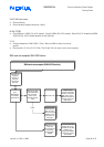
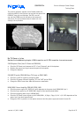
Z701 faulty / poor soldering
•
check the outgoing 13MHz IF on pin 30 N700 (SUMMA)
•
check the input 13MHz IF on pin 25, 26 N700 (SUMMA) . The attenuation between input and output is ≈20dBm
•
check the 13MHz IF on Z701, around 5dBm attenuation between signal-in and signal-out
•
check the soldering of Z701 or change it
•
check R717, R718, R719, C706 and the line resistance to ground (10KΩ with all components)
G700 UHF Oscillator faulty
•
check the UHF frequency on G700 for high spurious or deviation
•
check the UHF-VC on pin 21 N700 1,9V-3.2V DC depending of the channel
•
check the 5V VCP supply voltage on pin 13, 22 from N700 SUMMA
•
check R733 33KΩ, R730 5K6 Ω, R731 2K2Ω, C740 2,2nF
•
change the oscillator
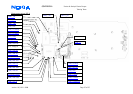
N700 SUMMA faulty / poor soldering
•
check the 13MHz reference frequency pin 15 N700. (No frequency deviation higher ±50Hz is allowed!)
•
check the power supply voltage VRX_2 2,8V DC pin 35 N600
•
check the incoming IF 71MHz pin 37,38 N700
•
check the 13MHz IF on pin 30(out),25, 26(in) N700 . The attenuation between input and output are ≈20dBm
•
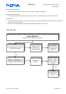
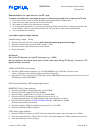
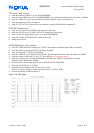
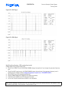
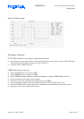
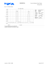
check the control-lines for the PLL pin 5, 6, 7 from N700 (see the diagrams below)
•
check the incoming VHF_LO frequency 464MHz pin 8 N700 if the 13MHz IF are deviated or not exist
measurable level approximate –20dBm!
•
Check the synth. power supply 2,8V DC pin 9, 19 N700 and VCC G700, G702
•
Check the VCP 5V DC pin 13, 22 N700
•
Check the control voltage for the UHF and VHF oscillator
(UHF pin 21 control voltage is channel dependent, pin12 2,2V DC on N700)
•
Check the soldering of N700 or change it
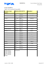
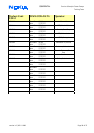
Figure 7: PLL-SCKL Signal