


SANYO supplies high-performance GaAs switching ICs that feature the industry's smallest package size and smallest number
of external components. SANYO discrete devices have been always leading the cell phone and mobile equipment markets.
SANYO is also developing devices that support the need for higher speeds and larger data capacities for image and video data
due to the inclusion of high pixel count cameras in this equipment.
3736
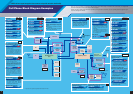
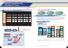
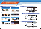
Handling More Data Even Faster. Supporting Needs for Higher Performance with
Peripheral Components
SANYO's Lineup of High-Reliability
Discrete Devices
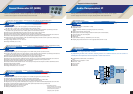
Whip antenna
Inner antenna
Antenna switches( GaAs MMIC)
Antenna switch
SPM3212
SPM3215
SPM3220
SPM3226
EC3H09B, EC3H07B
SBFP420B
Local switches
Power amplifier
Filter switches
(GaAs MMIC)
SPM3212
SPM3220
SPM3226
(Pch MOS)
MCH6305/MCH6307
ECH8603
(Pch MOS)
MCH6305/MCH6307
ECH8603
Li-ion
Battery
(Pch MOS)
ECH8601
ECH8603
Baseband
logic
Low-noise amplifier
SPM3212
SPM3220
SPM3226
OSC(NPN BiP)
Buffer amplifiers
EC3H10B
FS303
FS304
Filter switches for PCS and TDMA
SPM3212, SPM3220, SPM3226
Filter switches for TDMA
(GaAs MMIC)
SPM3211
SPM3212
Filter switches for TDMA
(GaAs MMIC)
SPM3212
SPM3220
SPM3226
Inner antenna
Diversity switches
(GaAs MMIC)
Duplexer
Antenna
Ext.
Antenna switch
Low-noise amplifier
PA module
Buffer amplifiers
(NPN BiP)
EC3H10B
FS303
FS304
Local switches
(GaAs MMIC)
SPM3212
SPM3220
SPM3226
Mixer
Filter
SPM3212
SPM3215
SPM3220
SPM3226
EC3H09B
EC3H07B
SBFP420B
OSC(NPN BiP)
Antenna
Inner antenna
Low-noise amplifiers
Power amplifier
CPH3106(PNP Bip.),
MCH3106(PNP Bip.)
MCH6305(Pch MOS)
MCH6307(Pch MOS)
CPH3106(PNP Bip.)
MCH3106(PNP Bip.)
MCH6305(Pch MOS)
Li-ion battery
Baseband logic
Antenna switches
SPM3212
SPM3220
Local switches
(NPN BiP)
SPM3212
SPM3220
SPM3226
Diversity switch
EC3H07B EC3H10B
SBFP405B SBFP420B
SBFP540B
SPM3215
SPM3226
EC3H09B
EC3H07B
SBFP420B
OSC
Buffer amplifiers
(NPN BiP)
EC3H07B
FS303
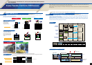
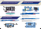
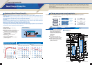
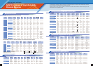
Thin-form package technology High signal-to-noise ratio technology
SSFP
SSFP
VSFP
VSFP
VTFP
VTFP
0.6 mm
0.46 mm
0.34 mm
SANYO achieved extremely thin packages by combining of the above technologies.
Total package height
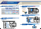
Establishment of and ultrathin wafer process (4 inch)
Gold loop and new software (M loop)
Earlier software: the chip and wire
were shorted together
100 m MAX
Gold loop and new software
φ20µm
Gold loop
WB loop height: 150 m maximum → reduced to 100 m maximum
SSFP
SSFP
VSFP
VSFP
VTFP
VTFP
Fame Fame
thicknessthickness
120 120 m
Frame bend width
130 m
Island frame thickness:
Reduced by 50 m !
Frame bending process:
Reduced by 80 m !
Total reduction: 130 m !
Thinner island frame and improved frame bending process
1.4✕1.4✕0.6 mm 1.2✕1.4✕0.46 mm 1.2✕1.4✕0.34 mm
Fame Fame
thicknessthickness
70 70
m
Fame Fame
thicknessthickness
70 70
m
Frame bend width
100 m
Frame bend width
50 m
Ultrathinner
Thinner
Ultrathinner
Thinner
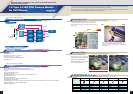
SANYO established an 80 µm ultrathin wafer process
by improving the wafer chamfering shape and introducing spin etching !!!
Introduction of B/G plus spin etching process!!
Factor workaround
B/G
Spin etching
Target thickness: 80 µmTarget thickness: 80 µm
Spin etching process
thickness: 40 µm
Target thickness: 80 µm
B/G process thickness: 350
µ
m
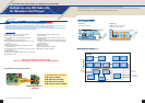
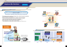
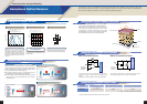
JFET noise component
Improved signal-to-noise ratio due to p-channel MOSFET development
Condenser microphone JFET structure
Gate sub
V
DD
protection resistor
Pch MOSFET
V
DD
300‰
1k‰
GND
V
IN
Result
Development
Effect
V
DDDD
V
DD
GNDGNDGND
V
IN
Input protection
diode
Input protection
resistor
V
IN
Protective
diode static
voltage
workaround
Drain pad
JFET
Source pad
Noise voltage (dBV)
Pch MOSFET
-113 to -114
-105 to -107 -1.5 to -3.5
JFET
Insertion loss (dBV)
Signal-to-noise ratio (dB)
62 to 64
-5.0 to -5.5 68 to 68.5
Signal-to-noise ratio evaluation
Gate
Drain
Source
Polysilicon resistor
transient characteristics
workaround
The high resistance polysilicon resistor (1 to 3 GΩ) used to stabilized the gate-source
potential accounts for a large portion of the JFET noise component.
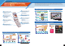
L / W = 3 µm / 1 mm
-106
-106.5
-107
-107.5
-108
-108.5
-109
-109.5
0.00 0.50 1.00 1.50 2.00 2.50 3.00 3.50 4.00
Smaller
Larger
Noise voltage (dBV)
R
GS
(GΩ)
0.14
0.12
0.10
0.08
0.06
0.04
0.02
0.00
0246810
Gate voltage (V)
Potential stabilization time (s)
2 GΩ
25 GΩ
90 GΩ
0.5
0.4
0.3
0.2
0.1
0
Vin Voltage (V)
0 0.5 1 1.5 2 2.5 3
Time (s)
Potential stabilization time
The potential stabilization time becomes under 1 second
in enhancement mode p-channel MOSFETs.
Enhancement mode
P-ch MOSFET
Potential stabilization time
Fame
thickness
120 m
Fame
thickness
70 m
Fame
thickness
70 m
Spin etching process
thickness: 40 µm
FETs for Cell phone ECM
Digital Cell Phone
0.8 GHz, 1.5 GHz
CDMA/TDMA (IS136)
PHS