


7
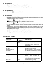
2.8 Accessory Interface
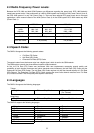
The table explains what kind of pins the phone supplies to the different accessories.
Pins
GND
1
Charge
2
GEN
I/O
3
Power
OUT
4
RX
(IN)
5
TX
(OUT)
6
ACC
ID
7
RS232
RTS
8
RS232
CTS
9
Audio
Out
10
Audio
IN
11
AGND
12
Charger
√ √
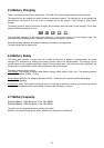
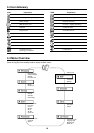
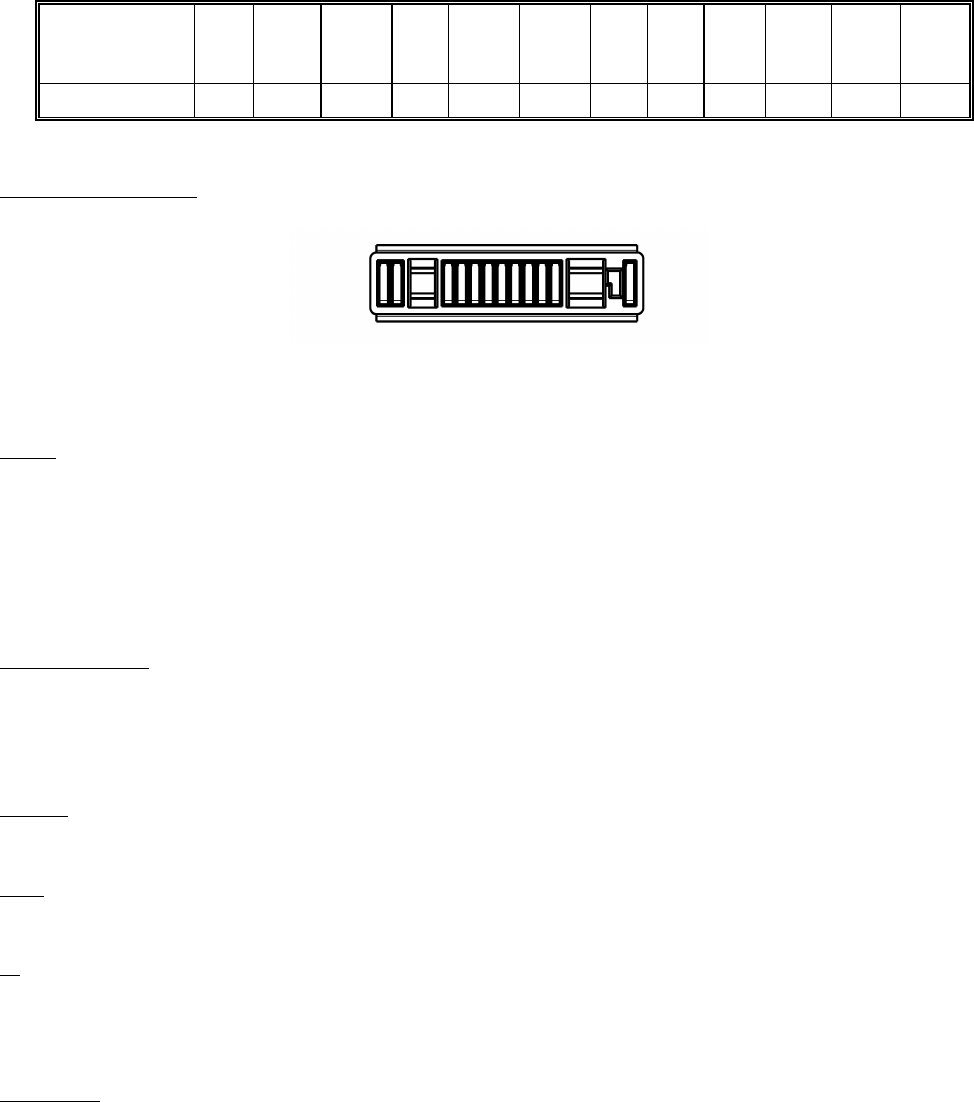
Connector layout
The connector comprises the following pins:
Audio
Audio In, Audio Out and Audio GND:
Audio IN:
Is a single ended input with a maximum sensitivity of 365 mVrms.
Audio OUT:
The single ended output delivers 0.8Vpp into a 1kΩ load.
These two signals are referred to as AGND.
RS232 Interface
5-pin interface: RX, TX, RTS(RFR), CTS and Gen I/O(DTR or DCD):
This is the communication interface to the Data cable “QN-3RS/USB”.
Pin 3 is connected to a general IO pin on the baseband digital chip. The functionality can be assigned on an
accessory by accessory basis to be input, output or interrupt.
Charge
The Charge pin represents the positive contact for the charging funtionality.
GND
The Ground pin represents the digital interface and charger return current.
ID
This pin shows the presence of an accessory and is also an analog ID for the accessory. Accessories which
provide charger functionality only do not support this pin and their presence is detected with a valid charger
voltage.
Power Out
Power-out has a different functionality with different accessories.
In the car-kit environment the ext. Vbat indicates that a phone call is accepted/in progress. This information is used
by the car-kit to power up the audio section of the car-kit, mute the car stereo and keep the car-kit powered up
even when the ignition is switched off.
Due to the fact that the ID of the accessory is detected first, the ACC power is not current limited (protected).
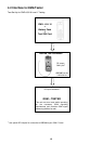
Connector view from base of phone
1
12