CM9740-CC1 | 11
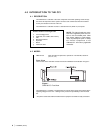
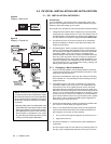
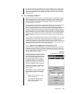
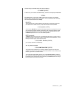
4.5 CONNECTING TO THE CONTROLLER
All system devices connect to the rear of the CM9740-CC1 controller. In general, any con-
nectable device that can be used with the CM9760-CC1 can also be used with the
CM9740-CC1.
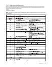
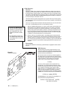
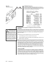
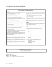
D-type, 9-pin connectors are used for COM 1 and COM 2, while the VGA card connector is
a 15-pin D-type connector. The PS/2 keyboard connection utilizes a standard 5-pin mini-Din
connector.
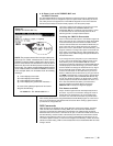
The printer connector (used mainly for system logging and printouts) is a 25-pin D-type
connector. A completely operational System 9740 will more than likely require the addition
of more equipment to the controller; namely, such items as a VGA monitor, or a PS/2 keyboard
and printer. To connect this equipment, simply plug the desired piece of equipment into the
appropriately labeled port. For connector information, refer to Figures 3 and 4.
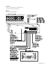
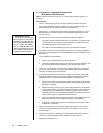
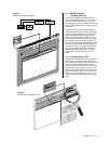
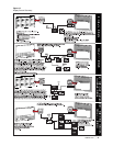
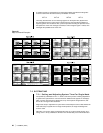
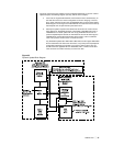
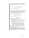
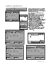
Figure 3
CM9740-CC1 Rear Connector Pinouts
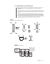
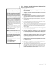
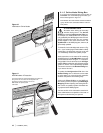
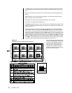
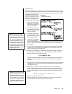
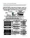
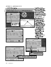
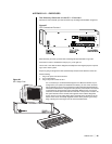
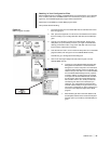
NOTE: When a Sercom
port is used to interface
multiple receivers, the
distance “D” between the
pick-off points and any
receiver should be 3 feet
(.91 m) or less
“D” (see note)
Figure 4
Multiple Receiver Hook-up