Rockwell Automation Publication 1412-UM001D-EN-P - September 2012 41
Display Modes Chapter 3
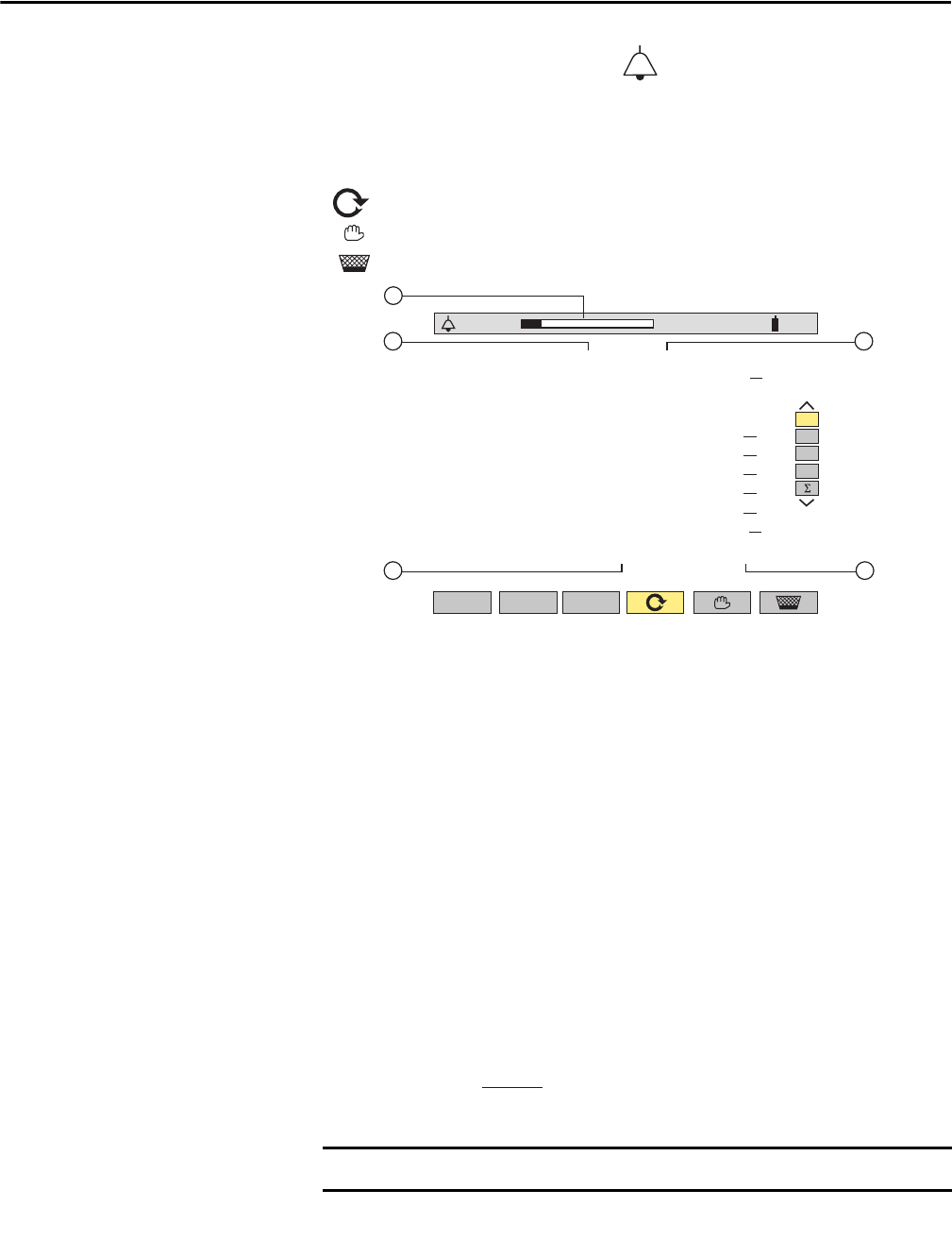
Alarm Mode
Press the alarm display mode button -
• Starts alarm capture
• Stops alarm capture
• Deletes all stored alarms
Alarm memory status bar (indicates available alarm storage memory)
Alarm target
Measurement parameter monitored
Maximum or minimum amplitude detected
Alarm duration
Use the Up/Down Cursor buttons to select an alarm.
Use the Left/Right Cursor buttons to display alarms within a period of time.
The threshold values must first have been programmed in the instrument
setup mode.
All the alarms recorded can be downloaded to a PC with the DATAVIEW
software. Up to 4096 alarms can be captured.
See Chapter
4 for information on using DATAVIEW software.
The Alarm values for PF, DPF, Tan, j, W, and VAR are absolute values.
The type of connection selected in the mode has no influence on the
possibilities of choices, target and monitored parameter. The user is
responsible for making pertinent choices.
07/25/02 11:27100
%
3L
L1
L2
L3
1
2 4
3
5
<
07/25/02
11:27
L1
L1
L1
L1
L1
L2
L1
L2
L3
L1
L1
Vthd
Vrms
Vthd
Vthd
Arms
Arms
Arms
Arms
Arms
Vrms
Vthd
23.1%
0V
34.3%
35.0%
1A
1A
0A
0A
0A
109V
35.1%
2s
1s24
1s
s
1s
1s5
1s3
1s9
1s9
1s8
3s37
3s
2/2
11:28
11:29
1
100
s
1
100
s
1
100
s
1
100
s
1
100
s
1
100
s
1
100


