type. As temperature increases the resistance value
decreases.
1. Remove the Right Side Panel.
NOTE: If right side panel is not accessible, this
component can be serviced by removing the Control
Panel.
2. Place a shielded thermocouple in the geometric
center of the oven cavity and determine the
temperature in the oven cavity.
3. Remove the probe lead wires from the solid state
temperature control.
4. Test the probe with an ohmmeter.
A. If the measured resistance values are inside
the given tolerance then the probe is
functioning properly.
B. If the measured resistance values are
outside the given tolerance then replace the
probe and retest.
1) Check oven for proper operation.
5. Reverse procedure to install.
TEMP (°F) OHMS* TEMP (°F) OHMS*
77 90,000 360 822
240 4,077 380 656
260 3,016 400 529
280 2,266 425 424
300 1,726 450 334
320 1,332 475 266
340 1,041
(*) Resistance in ohms ± 10%
GAS PRESSURE ADJUSTMENT
(units up to February 2015)
Disconnect the
electrical power to the machine and
follow lockout / tagout procedures.
1. Turn gas supply off at manual shutoff valve.
2. Remove the
Right Side Panel.
NOTE: If right side panel is not accessible, this
component can be serviced by removing the Control
Panel.
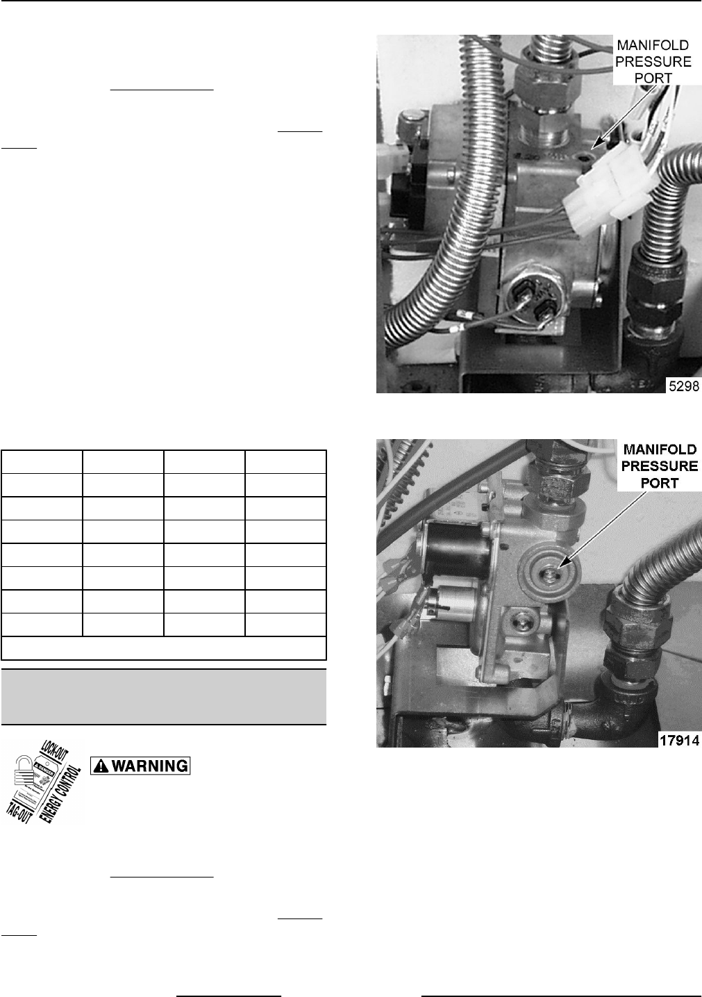
3. Remove the plug from the manifold pressure
port.
FIRST GENERATION UNIT SHOWN (Before April
2005)
SECOND GENERATION UNIT SHOWN (After April
2005 thru February 2015)
4. Install hose barb adapter and attach manometer
tube.
VC4G & VC6G SERIES FULL SIZE CONVECTION OVENS - SERVICE PROCEDURES AND ADJUSTMENTS
F24682 Rev. C (0315) Page 28 of 74


