COMPUTER CONTROL (VC4GC/
VC6GC)
Operation
Refer to the Instructions Manual for specific operating
instructions.
Setup Mode
NOTE: Use the setup mode to verify that the control
is configured to the factory settings which result in the
proper operation of the oven. If the CAL1 parameter
is other than zero, determine if it is still needed before
resetting to zero. See COMPUTER CONTROL
CALIBRATION (VC4GC/VC6GC).
Changing the C_F, InP1, rL1 & rH1
parameters will default all menus.
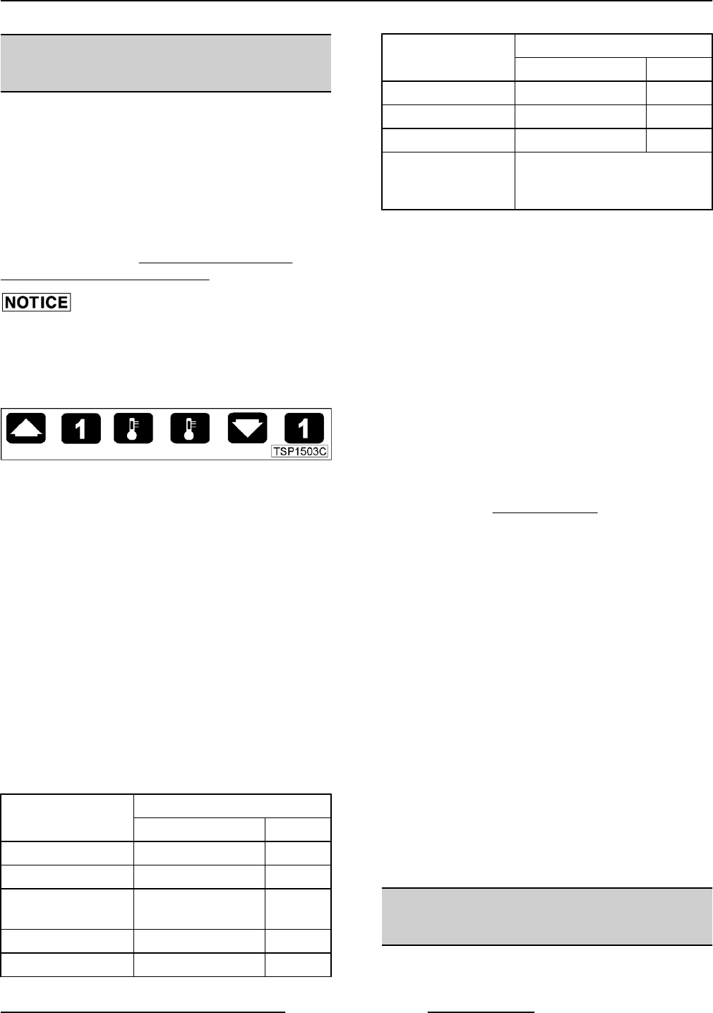
1. Use this key sequence to access the setup mode.
Up arrow; Rack 1; Temperature; Temperature;
Down arrow; Rack 1
Fig. 71
2. Once in the setup mode the display will alternate
between the parameter and programmed data.
• To change data to the factory setting, use
the arrow keys.
• To select the next parameter, press the
Rack 1 key.
• After the last Parameter and Data is viewed,
press the Rack 1 key a final time to exit the
setup mode and return to operations mode.
The current set point temperature will be
displayed.
• After 1 minute of no key activations, the
control will return to operation mode.
3. Listed are the parameters and data you should
find.
MENU
ALTERNATING ON DISPLAY
PARAMETER DATA
Celsius_Fahrenheit C_F F
Guard Band gb 4000
Temperature
Compensation
tcnP OFF
Input Type 1 InP1 J
Range Low 1 rL1 75
MENU
ALTERNATING ON DISPLAY
PARAMETER DATA
Range High 1 rH1 500
Hysteresis HYS1 3
Calibration Offset CAL1 0
Exit Setup Mode
and return to
Operation Mode.
set point temperature is
displayed or if call for heat,
dashes (----) displayed.
Probe Test
1. Set the control to 350°F.
2. Access the back of the control panel to
disconnect the probe lead wires.
3. Install a jumper wire across the probe terminals.
This will simulate room temperature.
A. If the heat light comes on and the actual
temperature is room temperature, replace
the probe.
B. If the heat light does not come on or the
actual temperature is not room temperature,
replace the control.
Solid State Relay Test
1. Remove the Right Side Panel.
2. Set the temperature to 350°F or high enough to
keep the heat ON for several minutes.
3. Check for +5 VDC on input side of SSR
(terminals 3 & 4).
A. If +5 VDC is present, continue to step 4.
B. If no voltage is present, computer control is
not functioning properly.
4. Check for 120 VAC at load side of SSR (terminals
1 & 2).
A. If no voltage is present, solid state relay is
not functioning properly.
1) Replace the SSR and check for proper
operation.
B. If 120 VAC is present, component is
functioning properly.
5. Re-assemble oven and check for proper
operation.
COMPUTER CONTROL
CALIBRATION (VC4GC/VC6GC)
1. Place a thermocouple in the geometric center of
the oven cavity.
VC4G & VC6G SERIES FULL SIZE CONVECTION OVENS - SERVICE PROCEDURES AND ADJUSTMENTS
Page 35 of 74 F24682 Rev. C (0315)


