


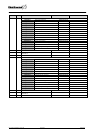

LOCATION 174 DEVICE STATUS FLAGS (2 segments)
This location contains specific status information of the GSM/GPRS module. If the option is
”On”, the status condition is true.
Segment 1
1 = On: Communication with GSM modem OK
2 = On: SIM card PIN is OK
3 = On: Logged in to the GSM network
4 = On: Sending SMS
5 = On: Using GSM audio connection
6 = On: Using GSM CSD connection
7 = On: Connected to GPRS network
8 = On: SIM card PUK code required
Segment 2
1 = On: Battery voltage failure
The NX-7002 measures and monitors battery voltage. It shares a
battery with the control panel.
2 = On: GSM PSU voltage failure
The main battery creates a 3.8 V power supply for the GPRS modem.
3 = On: Bus voltage failure
The bus supplies a 13.8 V voltage to the NX-7002.
4 = On : Communication channel failure
5 = On : Up/download session in progress
6 = On : Up/download session starting
7 = On : Reporting in Progress
8 = On : RSSI level at acceptable level
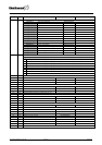
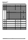
LOCATION 175 GSM MODEM MANUFACTURER (READ ONLY) (16 segments)
This location displays the manufacturer of the GSM/GPRS modem used on the NX-7002.
LOCATION 176 GSM MODEM MODEL (READ ONLY) (16 segments)
This location displays the model of GSM/GPRS modem used on the NX-7002.
LOCATION 177 GSM MODEM SOFTWARE REVISION (READ ONLY) (16 segments)
This location displays the software revision of the GSM/GPRS modem used on the NX-7002.
LOCATION 178 GSM MODEM SERIAL NUMBER (READ ONLY) (16 segments)
This location displays the serial number of the GSM/GPRS modem used on the NX-7002.
LOCATION 179 –
LOCATION 215 RESERVED
NX-7002 Installation manual Page 23 09/02/05