


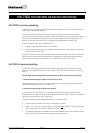

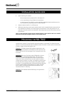
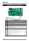
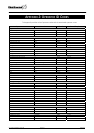
NX-7002 LAYOUT AND DESCRIPTION
9 8 1 2 3 4
1
1
11
10
7
5 7
6
DESCRIPTION
1 Future use (VVMIQ)
2 SIM card holder
3 GPRS modem
4 Connect antenna to this connector
5 Header for software upgrade
6 Connect to battery
7 Connect main panel battery leads to these connectors
8 Audio tap connector (CON5)
If the NX-7002 uses the voice channel for event reporting, the special audio cable
(included) needs to be stuffed between this connector of the NX-7002 and the Audio
Tap connector of the control panel.
9 Keypad bus terminals
10 Status LED’s
GSM in use: ON when events are send over the voice or data channel (Up/download)
PSU error: ON when the modem power source is to low
Reporting: ON when data is reported to the IP receiver or Mobile phone (SMS)
GPRS active: ON when the module is connected to the GPRS network and the first event is
send. It turns OFF when the module uses the voice channel
SIM error: ON when an incorrect PIN code is entered
GSM com: reserved
Network OK: reserved
Bus com: flashes when communicating on the NetworX bus
11 Green LED: ON when connected to TCP/IP receiver
NX-7002 Installation manual Page 33 09/02/05