


NTI RACKMUX RACKMOUNT ANSI TERMINAL DRAWER
6
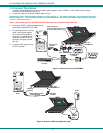
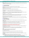
SUB D 25 male
connector
Rear View
RACKMUX-T15
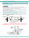
Attach local printer
either by parallel cable to Parallel
or by serial cable to Serial 2
9DF25DM-NUL-6
(supplied)
Rear View of CPU
SUB D 9 female
connector
VEXT-1,5-MM (supplied)
15HD male
Video Connector
IEC Powercord
(supplied)
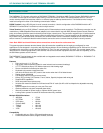
1.2 Connect The Cables
1. Connect a female SUB D 9 end of the null modem cable (supplied) to the "SERIAL 1" male SUB D 9 serial interface
connector on the RACKMUX (see Fig. 4).
2. Connect the other end of the null modem cable to a CPU.
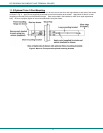
Alternatively, use an Ethernet cable to connect to a CPU (see Fig. 5). For direct connection, use a crossover cable (see
pinout on page 46). For connection through a Local Area Network (LAN), use a patch cable wired straight through (pin
1 to pin 1, pin 2 to pin 2, etc.).
Note: A serial cable (Figure 4) and Ethernet cable cannot both be connected at the same time.
3. Connect the VEXT-1.5-MM cable between the
ports labeled "MONITOR" and "VGA".
4. If connecting a printer, connect
either a serial printer cable to
the remaining male SUB D 9
connector or a parallel printer
cable to the female SUB D 25
connector (see page 3, items
19 & 20).
5. Connect the IEC power cord to
the IEC connector.
Figure 4 -Connect a CPU to the RACKMUX
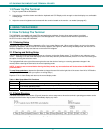
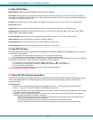
Figure 5- Connect to CPU using Ethernet cable
10Base T Ethernet Cable
Rear View of CPU
male RJ45
connector
male RJ45
connector
Rear View
RACKMUX-T15
10Base T
Ethernet
Cable
LAN
Server
Server
(crossover cable)
(patch cable)