


iii
TABLE OF FIGURES
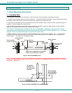
Figure 1- Mount RACKMUX to rack...................................................................................................................................................4
Figure 2- Position RACKMUX with clearance to open .......................................................................................................................4
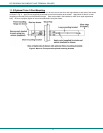
Figure 3- Mount to Telco post with optional mounting brackets.........................................................................................................5
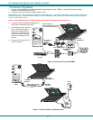
Figure 4 -Connect a CPU to the RACKMUX......................................................................................................................................6
Figure 5- Connect to CPU using Ethernet cable................................................................................................................................6
Figure 6- Function keys to press for submenus.................................................................................................................................7
Figure 7- OSD Controls ...................................................................................................................................................................40
Figure 8- US (English) Keyboard Layout .........................................................................................................................................43
Figure 9- Keyboard LED Indications ................................................................................................................................................43
Figure 10- Keys of the Number Pad ................................................................................................................................................44
Figure 11- Additional multi-function keys .........................................................................................................................................45
Figure 12- U.S. (English) keyboard with numeric keypad ................................................................................................................45
Figure 13- U.K. (English) keyboard with numeric keypad ................................................................................................................46
Figure 14- German keyboard with numeric keypad .........................................................................................................................46
Figure 15- RACKMUX with DC Power option ..................................................................................................................................47
Figure 16- Apply wires to terminal block ..........................................................................................................................................47
LIST OF TABLES
Table 1- Main Setup Menu Exit Functions .........................................................................................................................................7
Table 2- Programmable Keys ..........................................................................................................................................................12
Table 3- Color Setup Menu..............................................................................................................................................................13
Table 4- Color Palettes ....................................................................................................................................................................14
Table 5- Local Keyboard Commands in Native Mode......................................................................................................................16
Table 6- Serial Port (Serial 1) Connector Pin Assignments .............................................................................................................17
Table 7- Serial Port (Serial 2) Connector Pin Assignments .............................................................................................................17
Table 8- Printer Port Connector Pin Assignments ...........................................................................................................................17
Table 9- 10Base T Connector Pin Assignments ..............................................................................................................................17
Table 10- Commands Supported in ASCII Personalities .................................................................................................................18
Table 11- VT52 Mode Escape Sequences ......................................................................................................................................36
Table 12- Number Pad Keys............................................................................................................................................................44