


SpectraLink Corporation T1 Remote Module Installation
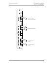
Link WTS – Link 3000 MCU
2. Site Preparation
The following steps must be completed before installing the system hardware. If the
steps are not already completed refer to each individual section for details.
1. At the local site, install and test Primary Shelf and Expansion Shelves. Refer to
Link WTS – Link 3000 MCU: Installation (72-0059-01) for information.
2. At the remote site:
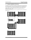
2.1 Install a two pair cable to each Base Station as designated on the building
floorplans.
2.2 Terminate the Base Station wiring with RJ-45 crimp-on plugs at the
designated Base Station locations.
2.3 Terminate the Base Station wire at the appropriate cross-connect demarc
blocks.
2.4 Terminate the analog or digital phone extensions from the phone system at
the appropriate cross-connect demarc block, and label the block.
2.1 Required Materials Provided by Customer
Rack - the shelves are designed to fit into a 19 inch mounting rack. Each shelf
measures 15” high by 19” wide by 9” deep, and weighs approximately 35 pounds
fully loaded. See Prepare Location for Shelves, in the Link WTS – Link 3000 MCU:
Installation document.
Backboard space – as an alternative to rack mounting, the shelves can be wall
mounted to ¾” plywood securely screwed to a wall.
Screws – required to mount the shelves to the wall, or to secure it in the rack. For
wall mount, six #10-5/8” panhead wood screws (or similar device) are required. For
rack mount, screws required are determined by the rack requirements; typically 10-32
or 1/4-20.
RJ-45 Cable - for network clocked T1 facilities, an RJ-45 cable is required to
connect the designated Master Clock T1 Module to the Intershelf Junction Panel.
Part Number: 72-0059-06-E.doc Page 11