


SpectraLink Corporation T1 Remote Module Installation
Link WTS – Link 3000 MCU
DISABLE
ALARM
1
2
3
4
5
CONN
A
NORMAL
DISABLE
ALARM
1
2
3
4
5
CONN
A
NORMAL
ALARM
1
2
3
4
5
RS-232
(RJ45)
(RJ45)
SC/A
SC/B
1 2 3 4 5 6 7 8 9 10 11 12
DISABLE
ALARM
1
2
3
4
5
CONN
A
NORMAL
DISABLE
ALARM
1
2
3
4
5
CONN
A
NORMAL
DISABLE
ALARM
1
2
3
4
5
CONN
A
NORMAL
DISABLE
ALARM
1
2
3
4
5
CONN
A
NORMAL
CONN
B
DISABLE
ALARM
1
2
3
4
5
CONN
A
NORMAL
CONN
B
DISABLE
ALARM
1
2
3
4
5
CONN
A
NORMAL
CONN
B
DISABLE
ALARM
1
2
3
4
5
CONN
A
NORMAL
CONN
B
DISABLE
ALARM
1
2
3
4
5
CONN
A
NORMAL
CONN
B
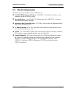
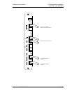
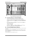
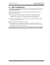
T1 Remote
Module
Expansion Shelf
Controller Slot 2
Interface Modules
Slots 3-12
ALARM
1
2
3
4
5
CRC-301
TIMING
MASTER
IN
SYNC
OUT
A
B
SYSTEM
CONTROLLER
SC/A
SC/B
EXPANSION
SHELF
CONTROLLER
DS1 A
LOS
LNKOK
DS1 B
LOS
LNKOK
Fully Loaded Remote Expansion Shelf
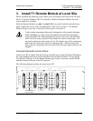
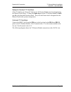
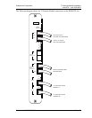
4.5 Connect Cables to T1 Remote Module
Connect T1 Remote Module to Expansion Shelf Controller
1. Using an RJ-45 cable, connect the Expansion Shelf Controller Port SC/A in the
T1 Remote Module (slot 1) to the
SC/A port on the Expansion Shelf Controller
(slot 2).
2. Using an RJ-45 cable, connect
SC/B in the T1 Remote Module to SC/B in the
Expansion Shelf Controller.
Connect T1 Facilities
3. Connect the T1 (
CSU) port to the DS1 A and DS1 B ports on the T1 Remote
Module. Port A controls slots 3-7. Port B controls slots 8-12.
4.6 Connect Multiple Remote Shelves
If the remote site consists of more than one remote shelf, the shelves must be connected
to each other.
Connect the IPC cable from the
Sync OUT Port of the T1 Remote Module on the first
shelf to the Sync IN Port of the T1 Remote Module on the next shelf. Repeat until all
shelves are connected.
Note that the
IN port of the first module is not used.
Part Number: 72-0059-06-E.doc Page 19