


SpectraLink Corporation T1 Remote Module Installation
Link WTS – Link 3000 MCU
4. Install System at Remote Site
4.1 Survey Site
Check the site to be sure pre-installation work has been completed correctly. This
includes:
• Location chosen for the shelves is adequate.
• Rack (if rack mounted) is properly secured or backboard (if wall mounted) is properly
prepared.
• Power is available.
• Wiring to Base Station locations has been pulled and correctly terminated.
• Phone lines for the Wireless Telephones are installed and properly terminated.
• Telephone system administrator is available to program the existing telephone
system.
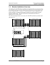
4.2 Install Shelves
Rack Mount
To install shelves in the rack, slide the shelves into the rack and secure them to the rack
using eight screws, 1/4 inch minimum length.
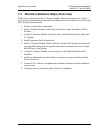
Wall Mount
At this point in the installation process, there should be a backboard securely fastened to
the wall and mounting screws partially inserted into the backboard. See Link WTS – Link
3000 MCU: Installation for more information.
To attach the shelves to the wall:
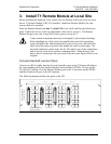
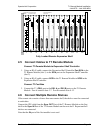
1. Remove all cards from the shelf. Do not mount the shelf with cards installed.
Cards contain components that may be damaged by electrostatic discharge.
Before handling any of the cards, attach the grounding strap (included in the
Administration Kit) to your wrist, and attach the other end of the strap to
ground. Handle cards only by their edges. Do not touch connector contact
areas. Do not lift cards by any of the components. Do not lay cards down on
their component sides. When laying a card down, place it component side
up, on top of the anti-static bag in which it was shipped.
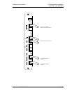
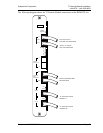
2. Position the MCS300 so that the six mounting screws are aligned with the six
keyhole openings in the back of the shelf.
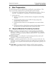
3. Slide the shelf down onto the screws to lock the shelf into place. Check that all
six screws are properly locked.
4. Tighten all six screws fully.
Part Number: 72-0059-06-E.doc Page 17