


SpectraLink Corporation T1 Remote Module Installation
Link WTS – Link 3000 MCU
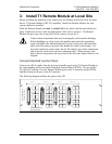
3. Install T1 Remote Module at Local Site
Before installing the hardware at the remote site, the Primary shelf at the local site must
have a T1 Remote Module (CRC301) installed. Install one Remote Module for each
remote shelf to be installed.
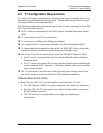
Slide the Remote Module into
slot 1 or slot 3-12 of any shelf, until the card clicks into
place. Tighten the screws at the top and bottom of the card to secure it. The Remote
Module can go in any slot, in any shelf of the system, except slot 2.
Cards contain components that may be damaged by electrostatic discharge.
Before handling any of the cards, the installer must attach the grounding
strap (included in the Administration Kit) to his or her wrist, and attach the
other end of the strap to ground. Only handle the cards by their edges. Do
not touch connector contact areas, do not lift cards by any of the components,
and do not lay cards down on their component sides. When laying a card
down, place it component side up on top of the anti-static bag in which it was
shipped.
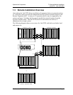
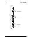
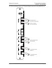
Connect Intershelf Junction Panel
Connect two RJ-45 cables from the System Controller ports in the T1 Remote Module to
the corresponding shelf ports on the Intershelf Junction Panel (JPI300). Be sure the RJ-
45 cable in Connector A on the Remote Module goes to the A connector on the JPI300,
and that Connector B goes to the B Connector.
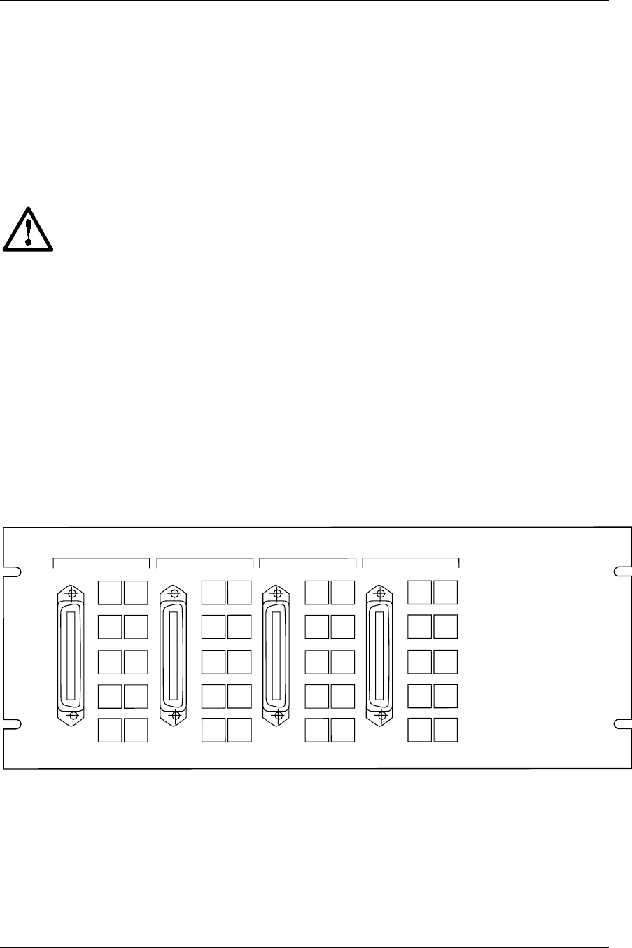
The following diagram outlines the ports on the JPI.
RJ-21 Connector to
System Controller
RJ-45 Connectors to
Shelf Controllers
SHELF 2-6
SHELF 7-1
1
SHELF 12-16
SHELF 17-20
AB
AB
AB
AB
2
3
4
5
6
7
8
9
10
11
12
13
14
15
16
17
18
19
20
AUX
Part Number: 72-0059-06-E.doc Page 14