10 PowerMonitor 1000 Unit
Rockwell Automation Publication 1408-IN001E-EN-P - September 2013
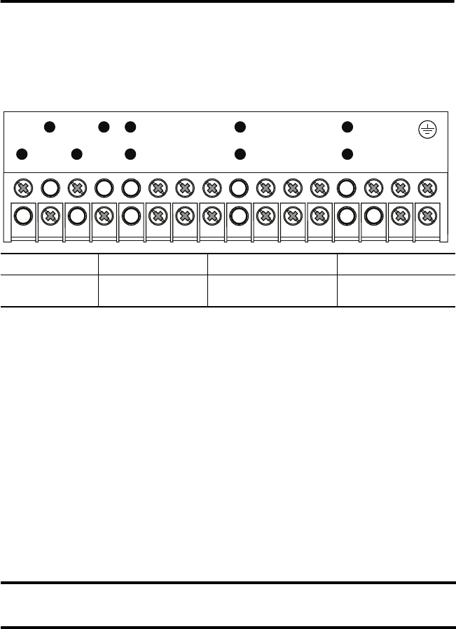
Wire the PowerMonitor 1000 Unit
The power monitor has finger-safe screw terminals with pressure plates for all wiring
connections.
Terminal Block Layout
Voltage Sensing
The PowerMonitor 1000 unit monitors a variety of three-phase and single-phase circuits.
Voltages of up to 600V AC line-to-line (347V AC line-to-ground) may be connected directly.
Higher voltages require potential transformers (PTs), also known as voltage transformers (VTs).
Wiring must conform to all applicable codes and standards. In particular, you must provide
suitable overcurrent protection with current and interrupting ratings selected to protect the
wiring.
Pay particular attention to correct phasing and polarity of voltage connections. The diagrams use
the dot convention to indicate transformer polarity. The dot indicates the H1 and X1 terminals
on the high side and low side of the transformer respectively.
When you wire a power monitor to existing PTs and metering devices, the voltage sensing
terminals of the power monitor must be connected in parallel with the voltage sensing terminals
of the existing metering devices.
The following wiring diagrams indicate typical voltage sensing connections to various types of
power systems.
Wire Type Wire Size Range Wires per Terminal Recommended Torque
Cu - 75 °C (167 °F) 0.33…0.21 mm
2
(22 … 14 AWG)
2 max per terminal, sol-sol or
str-str only (no mixed pairs)
0.8 N•m (7 lb•in)
Ungrounded three-wire Delta systems with line-to-line voltages between 347…600V AC may be directly
connected. However, if a ground fault occurs that raises the line-to-ground voltage above 347V AC, the unit
indicates a voltage over-range condition.
V1
V2
V3
VN
I1+
I1-
I2+
I2-
I3+
I3-
S1
NC
S2
CF
SCOM
CF1
L2L1
YKZ


