Installing Additional Components
Installing Processors and Memory
Chapter 3
41
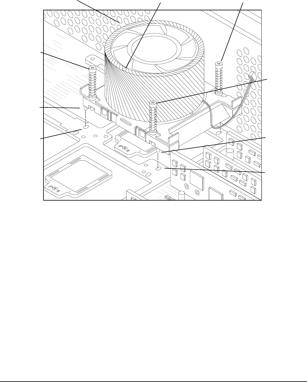
Figure 3-19Installing the Turbo Fan and Processor Assembly
Step 9. Use the special processor tool shipped with processor assemblies to lock the processor in place on
the system board. To do this, insert the special processor tool into the hole that runs down the side
of the heatsink and rotate it clockwise 180 degrees.
Step 10. Slide the sequencing retainer plate toward the front of the system.
Step 11. Tighten the four captive screws of the heatsink in the order shown in Figure 3-19. Tighten each
screw 1/2 turn, and then tighten the next screw. Continue this sequence until the heatsink is
secured to the system board.
Step 12. Connect the power cable for the processor turbo fan to its connector on the system board.
Step 13. Slide the CPU power module on the system board metal mounting bracket so that the power
module connector aligns with the connector on the processor. Align the two mounting screw holes
on the power module with their screw holes on the system board’s metal mounting bracket. Screw
in the power module mounting screws.
Step 14. Connect the CPU power module power cable.
Step 15. Place the processor airflow guide in position.
Step 16. Install the chassis top cover. Refer to “Replacing the Top Cover” on page 26.
cpu1noppm3
Screw 2
(Tighten
second
Locator
Post
Locator
Hole
Screw 4
(Tighten
last)
Locator
Post
Locator
Hole
Screw 1 (not shown)
(Tighten first)
Insert Processor
Tool Here
Screw 3
(Tighten third)


