


IQ8Wireless transponder for wall mounting
FB 798941 / 10.06 33
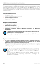
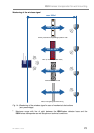
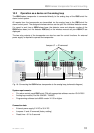
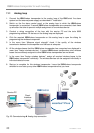
10.2 Operation as a device on the analog loop
The IQ8Wireless transponder is connected directly to the analog loop of the IQ8Control fire
alarm control system.
All reports from the transponder are transmitted via the analog loop to the IQ8Control fire
alarm control panel. The assigned wireless devices can be split into individual detector zones.
If a report is sent from a IQ8Wireless base, the detector zone and detector number of the
IQ8Wireless base (incl. fire detector IQ8Quad) or the wireless manual call point IQ8MCP are
displayed.
The two relay outputs of the transponder can also be used for control functions. An external
power supply is required to operate the transponder.
I
Q
8
C
o
n
t
r
o
l
I
Q
8
C
o
n
t
r
o
l
A+
B+
A-
B-
++ - -
IN OUT
U
B
-
+
9 V.....30 V DC
+-
J1
J2
PE PE
++ - -
IN OUT
U
B
-
+
9 V.....30 V DC
+-
J1
J2
PE PE
Jumper J1 + J2 removed
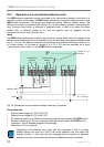
Fig. 18: Connecting the IQ8Wireless transponder to the analog loop (schematic diagram)
System requirements:
• Fire alarm control panel IQ8Control C/M with appropriate software version V3.04 R001
• Analog loop module (Part No. 804382 / 784382)
• Programming software tools 8000 version V1.09 or higher
Connection data
• External power supply 9 V DC to 30 V DC
• Jumpers J1 and J2 removed (factory setting)
• Reset time = 0.2 to 3 seconds