


IQ8Wireless transponder for wall mounting
FB 798941 / 10.06 35
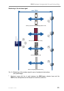
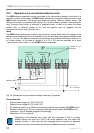
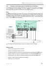
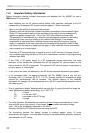
10.3.1 Connection of two detector zones for individual fire and fault alarm
The application provides the separate transmission of a fault alarm (e.g. battery low message)
and an additional fire alarm message. The fault message is non-latching and is resetted
automatically after the cause of the fault alarm is not present anymore.
Reset
The IQ8Wireless transponder is reset to the functional, normal status when the voltage of the
detector zone “Fire” drops below 5V for at least 60ms (e.g. by switching the fire zone on/off).
The detector zone can also be reset via an external reset button (refer to c) or a relay contact.
In this case a voltage of 9 to 30 V DC must be switched for at least 1 second at the input
(input +/-) of the IQ8Wireless transponder.
-
+
Detector zone
C
NONC
C
NCNO
R P
"Fault"
-
+
Detector zone
"Fire"
FACP
10K
10K
1K
R1 R2 R3
J1
J2
Sa-Feuer
Common fire
Sa-Stör
Common fault
Jumper J1 + J2
inserted
-
+
9 V - 30 V DC
Reset
1
-
+
Eing
-
+
U
B
Fig. 20: Wiring of two individual detector zones for fire alarm and fault (Example)
Connection data
• External power supply 9 V DC to 30 V DC
• Detector zone voltage 9 V DC to 30 V DC
• R1 quiescent resistor (e.g. 10KΩ for conventional detector zones System 8000/IQ8Control)
• R2 alarm resistor (e.g. 1KΩ for conventional detector zones System 8000/IQ8Control)
• R3 fault resistor (e.g. 10KΩ for conventional detector zones System 8000/IQ8Control)
• Jumpers J1 and J2 inserted (supplied with package)
• Reset time = 0.2 to 3 seconds