


IQ8Wireless transponder for wall mounting
38 FB 798941 / 10.06
10.6 Inputs
-
+
Eing
-
+
U
B
Schnittstelle
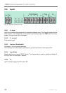
1 2 3 4 5 6 PR
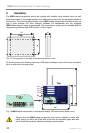
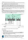
Fig. 23: Position of the terminals
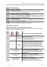
10.6.1 R - input
Input for connecting the transponder to a standard detector zone. This input is required for the
reset function. If the transponder is connected to the analog loop of the IQ8Control fire alarm
system, the input must not be connected.
10.6.2 P - terminal
Free terminal point
10.6.3 Interface (Schnittstelle)
No function – do not connect terminals.
This interface is for future feature extensions (e.g. direct connection of the service PC).
10.6.4 Input (Eing)
Reset input for an external RESET signal. The transponder is reset by applying voltage of
9V DC to 30V DC for at least 1 second.
10.6.5 U
B
Input for power supply 9 V DC to 30 V DC.