


IQ8Wireless transponder for wall mounting
FB 798941 / 10.06 41
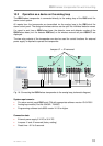
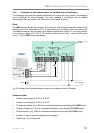
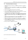
11.2 Conventional detector zone input
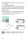
1. Connect the external power supply to the IQ8Wireless transponder as described in
"Installation".
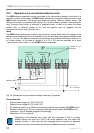
2. Connect the service PC to the terminals for the analog loop of the IQ8Wireless
transponder via the panel interface (Part No. 789862) and start the tools 8000
programming software.
3. Conduct a wiring recognition with the service PC and tools 8000.
4. Click the required IQ8Wireless transponder to open the programming dialog.
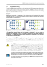
5. In the menu item “Measure signal strength” check if the quality of the wireless
transmission between the transponder and the base is adequate.
6. All the IQ8Wireless bases that this IQ8Wireless transponder has recognised are displayed
in menu item "Assign wireless devices“. If several IQ8Wireless transponders exist,
IQ8Wireless bases that are already assigned to other IQ8Wireless transponders are not
shown.
7. In the menu item “Assign wireless devices“, assign all required IQ8Wireless bases to the
IQ8Wireless transponder individually incl. menu option “Read detectors”.
8. Remove the connection on the terminals on the analog loop of the IQ8Wireless
transponder and disconnect the transponder for approx 5 seconds from power supply.
9. Connect the IQ8Wireless transponder to the conventional detector zone input of the fire
alarm system as described in “Installation”.
10. Start-up is complete for this IQ8Wireless transponder.
esserbus
®
4Z/2R
esserbus
®
-
transponder
Conventional
detector zone
Panel
Interface
789862
805595
++--
IN OUT
Service PC
Fig. 26: Commissioning
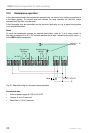
Î
Conventional zone input