SAMSUNG Proprietary-Contents may change without notice
5. Circuit Description
This Document can not be used without Samsung's authorization
5-1
< RF Circuit Description of SGH-T519 >
1. FEM (F100)
==> Switching Tx, Rx path for GSM850, EGSM900, DCS1800 and PCS1900
controlled by logic.
Integration of GSM850, EGSM900, DCS1800 and PCS1900 RX SAW Filters.
To convert Electromagnetic Field Wave to Acoustic Wave and the pass the specific
frequency band.
- for filtering the frequency band 824 ~ 849 / 869 ~ 894 MHz
- for filtering the frequency band 880 ~ 915 / 925 ~ 960 MHz
- for filtering the frequency band 1710 ~ 1785 / 1805 ~ 1880 MHz
- for filtering the frequency band 1850 ~ 1910 / 1930 ~ 1990 MHz
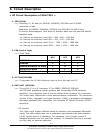
2. FEM Control Logic
==> Truth Table
VC1 VC2 VC3
GSM850 Rx Mode L L H
EGSM900 L L L
GSM850/EGSM900 Tx Mode L H L
DCS/PCS Rx Mode L L L
DCS/PCS Tx Mode H L L
3. VC-TCXO(TCX400)
==> To generate the 26 MHz reference clock to drive the logic and RF.
4. SKY74137 (UCD100)
==> The sky74137 is a RF tranceiver IC for GS850, EGSM900 DCS1800
and PCS1900 quardband cellular systems, and incorporates EDGE tranceiver
capabillity, and integrates most of the low power silicon functions of a tranceiver.
The receive path implements a direct downconversion architecture. The transceiver
consists of four integrated Low Noise Amplifiers (LNAs), a quadrature demodulator,
selectable baseband filter bandwidths, and lowdroop DC Offset Correction (DCOC)
sequencer.
- RX Function
Four LNAs which support different bands of operation have separated differential
inputs. The LNA outputs feed into a quadrature demodulator that down-converts
the RF signals directly to baseband. The baseband I and Q paths consist of
cascaded amplifiers and low pass filter sections. All baseband filtering is provided
on-chip using no external capacitors.


