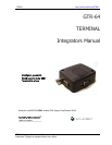
GTR64 http://www.matrix.es/GTR64
7.3.2 Antenna type
Make sure that you choose the right type of antenna for the modem. Consider the following
requirem
ents:
the antenna must be designed for the one of the frequency bands in use; please ask your network
e informations:
• GSM 850/900 MHz
00 MHz;
alue should be less than 3:1 to avoid damage to the modem.
east
se
of the signal received by the modem. The modem’s peak output
ower can reach 2W.
d strength
ay be up to 70V/m and at 1m it will have reduced to 7V/m. In general, CE-marked products for
cial areas, and light industry can withstand a minimum of 3V/m.
o
that the antenna cable is as short as possible. The Voltage Standing-
Wave Ratio S the effectiveness of the antenna, cable and connectors. In addition,
if you use a d nna cable and the antenna connector, it is crucial that the
extension cables, connectors and
of signal power.
.3.5 Possible communications disturbances
ossible communication disturbances include the following:
be a particular problem inside buildings, especially if the walls are thick and
inforced.
Hand-over occurs as you move from one cell to another in the GSM network. Your mobile application
ell to the next. Hand-over can briefly interfere with communication and may
use a delay, or at worst, a disruption.
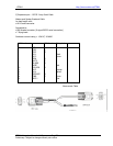
Power supply, all type of antennas (indoor, outdoor, high gain, etc…), cables and DIN adapter
•
provider for mor
• GSM 1800/19
• the impedance of the antenna and antenna cable must be 50Ω;
• the antenna output-power handling must be a minimum of 2W;
• the VSWR v
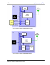
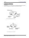
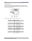
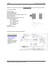
7.3.3 Antenna placement
The antenna should be placed away from electronic devices or other antennas. The recommended
minimum distance between adjacent antennas, operating in a similar radio frequency band, is at l
50cm. If signal strength is weak, it is useful to face a directional antenna at the closest radio ba
station. This can increase the strength
p
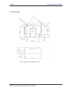
RF field strength varies with antenna type and distance. At 10cm from the antenna the fiel
m
residential and commer
7.3.4 The antenna cable
Use 50Ω impedance low-loss cable and high-quality 50Ω impedance connectors (frequency range up t
2GHz) to avoid RF losses. Ensure
(V WR) may depend on
n a apter between the ante
antenna cable is a high-quality, low-loss cable. Minimize the use of
adapters. Each additional cable, connector or adapter causes a loss
7
P
• Noise can be caused by electronic devices and radio transmitters.
• Path-loss occurs as the strength of the received signal steadily decreases in proportion to the
distance from the transmitter.
• Shadowing is a form of environmental attenuation of radio signals caused by hills, buildings, trees or
even vehicles. This can
re
• Multi-path fading is a sudden decrease or increase in the signal strength. This is the result of
interference caused when direct and reflected signals reach the antenna simultaneously. Surfaces such
as buildings, streets, vehicles, etc., can reflect signals.
•
call is transferred from one c
ca
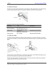
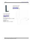
7.4 Accessories
The GTR64 has been type approved together with a range of accessories including:
GTR64 Integrators Manual V.1.2 Pag. 29
Preliminary. Subject to change without prior notice