⎯ 112 ⎯
6 F 2 S 0 8 5 7
y
p
=
=
1
5
1
1
1
BIS
1W4 1
BISW 5 1
::
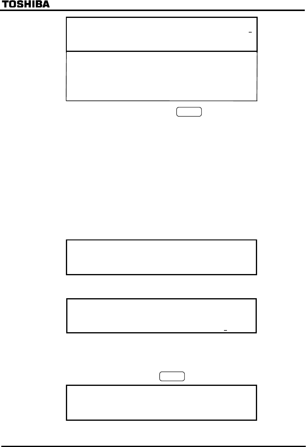
• Enter 1 (= Normal) or 2 (= Inverted) and press the
ENTER
key for each binary input.
4.2.6.9 Binary Output
All the binary outputs of the GRT100 except the tripping command, and the relay failure signal are
user-configurable. It is possible to assign one signal or up to six ANDing or ORing signals to one
output relay. Available signals are listed in Appendix B.
It is also possible to attach a drop-off delay time of 0.2 seconds to these signals. The drop-off delay
time is disabled by the scheme switch [BOTD].
Appendix D shows the factory default settings.
To configure the binary output signals, do the following:
Selection of output module
•
Press 8 (= Binary output) on the "Setting (change)" screen to display the "Binary output"
screen. The available output module(s) will be shown.
y
p
1=IO
2=IO
3
• Press the number corresponding to the selected output module to display the "Binary output"
screen.
/3 Binar
out
ut (IO2)
Select BO ( 1- 13)
Select No.=
Note: The setting is required for all the binary outputs. If any of the binary outputs are not to be used,
enter 0 for the logic gates #1 to #6 when assign signals.
Selecting the output relay
•
Enter the output relay number and press the
ENTER
key to display the "Setting" screen.
/4 Setting (BO1
of
IO2)
1=Logic gate t
e&dela
timer
2=Input to logic gate


