


8
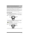
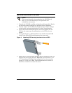
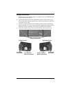
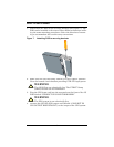
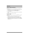
Wiring access doors on each end of the POD allow access to the wiring
compartments by opening the top and rear of the POD. Each access
door is retained using two Phillips head screws.
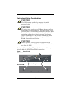
The center screw and center panel should not be removed.
Figure 6 Removing wiring access doors
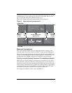
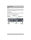
Electrical Connections
The wiring compartments provide terminal blocks to connect Line,
Neutral, and Ground for both the UTILITY input and LOAD output.
The cable sizes and distribution methods used during installation are
subject to local/national electrical codes of practice, and therefore are
not detailed here. Table 1 details the standard current ratings.
Properly Grounded (Earthed) Equipment Provides Multiple Benefits
High quality Ground (Earth) connections are required for the equip-
ment ground conductors (Protective Earth) (power system earth con-
nection) to provide for safe operation of the UPS and connected loads
and to reduce electrical noise. Conduit used alone without a grounding
conductor wire is not an acceptable connection. Size Ground (Protec-
tive Earth) conductors equal in size to circuit conductors.
For wiring information, please refer to Table 1.
CAUTION
- RISK OF ELECTRIC SHOCK, SO NOT REMOVE COVER. NO USER
SERVICEABLE PARTS INSIDE. REFER SERVICING TO QUALIFIED SERVICE PERSONNEL.
CAUTION
- RISK OF ELECTRIC SHOCK, THIS UPS RECEIVES POWER FROM
MORE THAN ONE SOURCE-DISCONNECTION OF THE AC SOURCES IS REQUIRED
TO DE-ENERGIZE THIS UNIT BEFORE SERVICING.
CAUTION
- FOR USE IN A CONTROLLED ENVIRONMENT. REFER TO MANUAL FOR
ENVIRONMENTAL CONDITION.
Model No. : MP2-115HW
Desc. : Micro Pod
Input : 120VAC 12A
50/60Hz, 10
Ouptut : 120VAC 12A
50/60Hz, 10
MADE IN TAIWAN 612-XXXXX-00
C US
LISTED
91N6
U.P.S. Accessory
U
L
POWER OUTPUT DISTRIBUTION
1.) ENSURE MAINTENANCE BYPASS LAMP IS ILLUMINATED.
2.) SWITCH TO MAINTENANCE BYPASS POSITION.
(LOAD IS NOW UNPROTECTED!)
3.) TURN UPS OFF AND DISCONNECT UPS CORDS FROM POD.
4.) UPS IS NOW AVAILABLE FOR MAINTENANCE
MAINTENANCE OF UPS
1.) MAKE LINE CORD CONNECTION TO UPS SIDE OF POD.
2.) TURN ON UPS BY ITS START INSTRUCTIONS.
3.) ENSURE UPS LAMP IS ILLUMINATED.
4.) SWITCH TO UPS POSITION
(LOAD IS NOW PROTECTED BY UPS!)
INSTALLATION OF UPS
Do NOT remove the
center screw
REAR VIEW
TOP VIEW
Access
Door
Access
Door
Remove
Screws
Remove
Screws