FIGURES
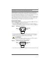
Figure 1 UPS mode of operation . . . . . . . . . . . . . . . . . . . . . . . . . . . . 4
Figure 2 Utility/maintenance bypass mode . . . . . . . . . . . . . . . . . . . 4
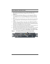
Figure 3 2U Hardwire POD with rack mounting brackets . . . . . . . 5
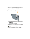
Figure 4 Attaching POD securing brackets to rear of UPS . . . . . . . 6
Figure 5 Conduit entry. . . . . . . . . . . . . . . . . . . . . . . . . . . . . . . . . . . . 7
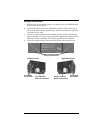
Figure 6 Removing wiring access doors . . . . . . . . . . . . . . . . . . . . . .8
Figure 7 Attaching POD to securing brackets . . . . . . . . . . . . . . . . 10
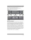
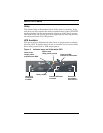
Figure 8 Indicator lamps on 2U Hardwire POD. . . . . . . . . . . . . . . 12
TABLES
Table 1 Breaker specifications . . . . . . . . . . . . . . . . . . . . . . . . . . . . 15


