


LBI-38965 INSTALLATION
20
4. INSTALLATION
4.1. HARDWARE INSTALLATION
Turn off the power before removing or installing VMEbus boards. Removing or reinstalling the boards while the power is
on will damage the boards.
This section describes the physical installation of the BCU/CAL. Other configuration is performed during
manufacture, and the information necessary is provided in Appendix B.
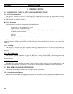
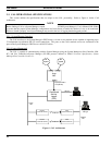
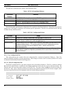
Follow these steps to connect a BCU/CAL to an IMC for the first time (except where indicated otherwise, these steps
apply to all configurations; BCU only, CAL only, or BCU and CAL):
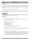
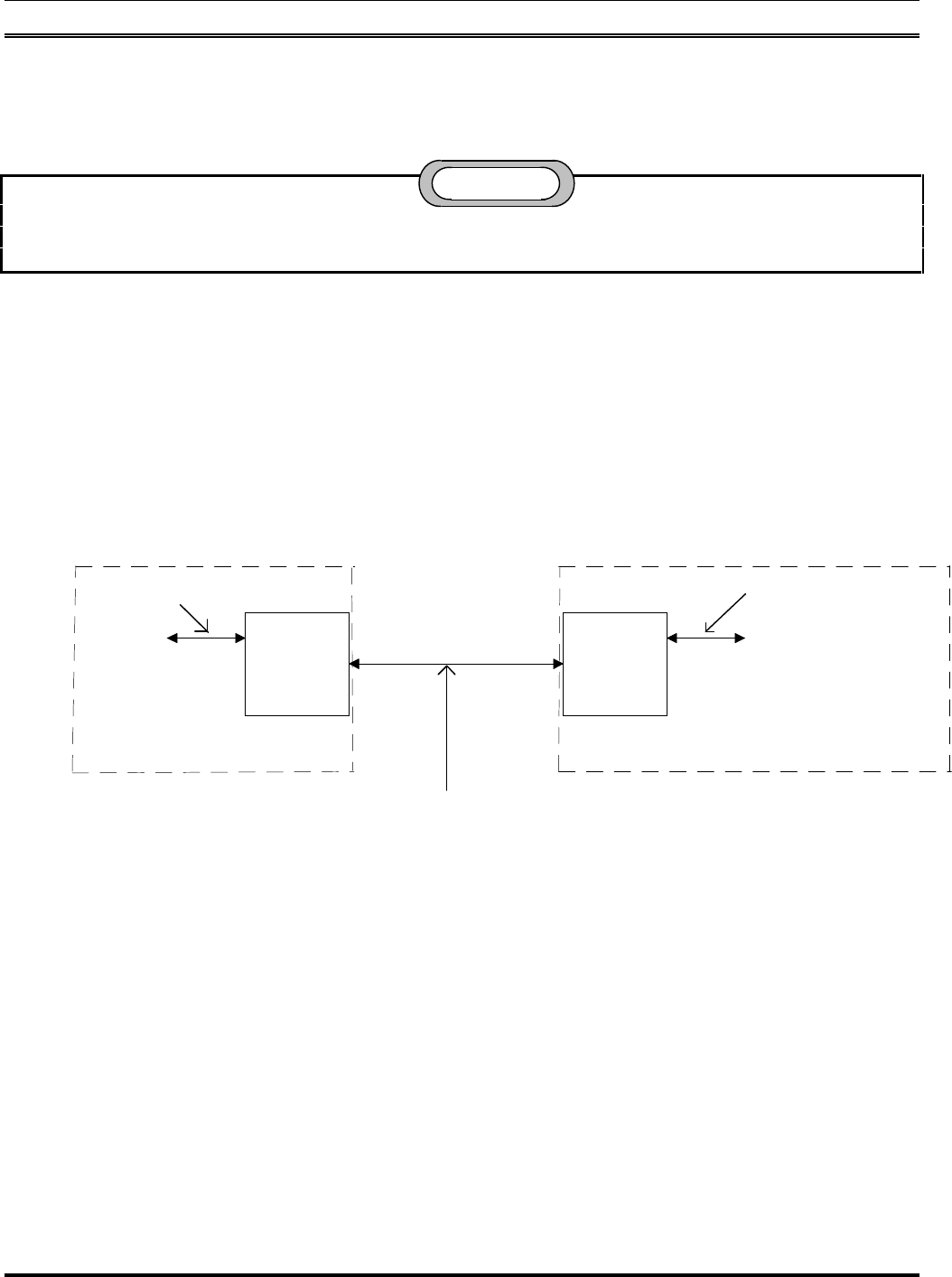
Using the LAPB cable provided, connect the BCU/CAL's CAM control port 0, a female DB-25 connector located on the
rear of the BCU enclosure, to the lower connector on the IMC backplane which corresponds to the slot in which the CAM
resides. The cable is keyed so that it fits properly only when it is correctly oriented.
19D903628P71
P72
P73
CAM Control
Audio Concentrator
at IMC
Data Concentrator at
BCU/CAL Equipment Rack
P2 P1
19D903880P120-129
BCU/CAL
and will correspond with
This will be plugged into
PA2XX on the backplane
the slot in which the CAM
control card is located.
CAM Control
Port 0
J1
J14 J9
J1
19C852327G1
19D903531P1
BCU/CAL Equipment Rack
IMC Equipment Rack
A6 2203710G1
Figure 5 - BCU/CAL to IMC
Next, connect the console terminal to the female DB-25 connector labeled "SERIAL PORT 1/CONSOLE" on the
TVME-712/M transition module located in the rear of the BCU/CAL enclosure. (For reference, the BCU/CAL is delivered
preconfigured from the factory in a 19-inch rack.) Connect the other end of this cable to the console terminal's "host" port,
or equivalent. If a PC is used as the console terminal, then a DB-9 adapter may be needed. In either case, the serial cable
for the console is wired straight-through.
Configure the console terminal for the communications parameters below.
• 9600 Baud
• No Parity
• 8 Data Bits
• 1 Stop Bit
CAUTION