


MB3891
4
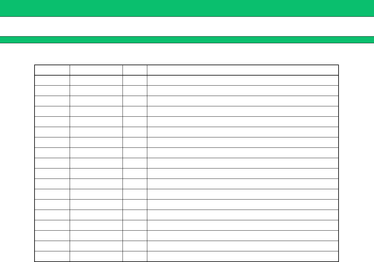
(Continued)
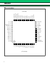
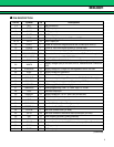
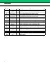
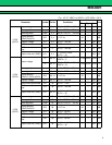
Pin No. Symbol I/O Descriptions
42, 43 VBAT4 Supply voltage for LDO4.
44 CONT4 I OUT4 output voltage selection (“L”=2.8 V,“H”=2.5 V).
45 SW1-OUTPUT O Output of general purpose switch number 1 (Drain).
46 SW1-INPUT I Input of general purpose switch number 1 (Source).
47 SW3-OUTPUT O Output of general purpose switch number 3 (Drain).
48 SW3-INPUT I Input of general purpose switch number 3 (Source).
49, 50 N.C. Non connection.
51 SW2-OUTPUT O Output of general purpose switch number 2 (Drain).
52 SW2-INPUT I Input of general purpose switch number 2 (Source).
53 SW1-ON I General purpose switch number 1 Enable (Active high).
54 SW2-ON I General purpose switch number 2 Enable (Active high).
55 SW3-ON I General purpose switch number 3 Enable (Active high).
56 CONT3 I OUT3 and OUT4 supply voltage Enable (Active high).
57 CONT5 I OUT5 supply voltage Enable (Active high).
58 OUT5 O Output terminal of LDO5.
59 GND5 LDO5 ground pin.
60, 61, 62 VBAT3 Supply voltage for LDO and LDO5.
63, 64 N.C. Non connection.