


MB3891
7
■
■■
■
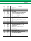
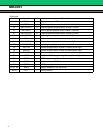
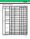
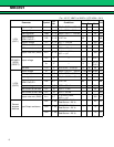
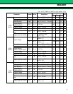
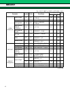
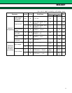
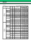
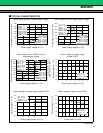
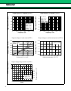
ELECTRICAL CHARACTERISTICS
(Ta = +25 °C, VBAT1 to VBAT4 = VCC-VSIM = 3.6 V)
* : Standard design value
(Continued)
Parameter Symbol Pin No. Conditions
Value
Unit
Min. Typ. Max.
General
Shutdown supply
current
I
BAT1
8, 9, 10, 11,
20, 42, 43,
60, 61, 62
UVLO = “L”,
BACKUP UVLO = “L”
80 µA
I
BAT2
8, 9, 10, 11,
20, 42, 43,
60, 61, 62
UVLO = “L”,
BACKUP UVLO = “H”
160 µA
Standby supply
current
I
BAT3
8, 9, 10, 11,
20, 42, 43,
60, 61, 62
All circuit’s = On
(No load)
400 µA
Operating ground
current
I
GND
4, 5, 19,
32, 59
All circuit’s -VSIM =
On Max. load on all
regulators
10 mA
UVLO threshold
voltage
V
THH
8, 9, 10, 11,
20, 42, 43,
60, 61, 62
OUT1 = ON 2.980 3.080 3.180 V
V
THL
8, 9, 10, 11,
20, 42, 43,
60, 61, 62
OUT1 = OFF 2.780 2.880 2.980 V
BACKUP UVLO
threshold voltage
V
THH
8, 9, 10, 11,
20, 42, 43,
60, 61, 62
V-BACKUP = ON 2.980 3.080 3.180 V
V
THL
8, 9, 10, 11,
20, 42, 43,
60, 61, 62
V-BACKUP = OFF 2.580 2.680 2.780 V
Input voltage
V
IH 16, 56, 57
0.7 ×
OUT1
OUT1 V
VIL 16, 56, 57 0
0.3 ×
OUT1
V
V
IH 14, 15, 44
0.7 ×
VBAT
VBAT V
V
IL 14, 15, 44 0
0.3 ×
VBAT
V
VIH 26, 27
0.7 ×
VCC-VSIM
VCC-VSIM
V
V
IL 26, 27 0
0.3 ×
VCC-VSIM
V
Pull-up resistor
R
PU 17 15* kΩ
R
PU 14, 57 200* kΩ
Pull-down resistor RPD 15, 53, 54, 55 200* kΩ