Installation
7/99 4909 CPVC Conductivity Cell Insertion/Removal Assembly– Operations Manual 13
3. Using a strap wrench on the mounting nipple, tighten the assembly an additional 1-1/2 to 2 turns. Do
not use stillson or chain type wrenches as they may damage and weaken the CPVC plastic. Do not use
the valve handle for leverage.
4. Close the ball valve; handle perpendicular to valve.
A purge port is provided on the removal device housing. Water or some other fluid source can be piped to
this port for the purpose of cleaning out the valve assembly from accumulated debris. For most
conductivity applications, the process stream will not have high particle content and the purge port is not
used.
If purging is required remove plug and install a purge line to the ¼” NPT opening. Note that the purge fluid
temperature and pressure must not exceed the 4909 Assembly temperature and pressure specifications as
shown in Fig. 1-1. Also, the purge line must have a shutoff valve located near the removal device.
Another use for the purge port can be realized if a pressure gage is installed in the ¼” NPT opening. It will
serve as a local indication of process pressure to confirm that the pressure is below 50 psig during insertion
or removal of the cell.
Make sure the bushing and washer are in place on the support tube, then feed the cable of the 4908
Conductivity Cell through the support tube and turn the tube hand tight onto the conductivity cell. Using a
strap wrench, tighten the 4908 Cell an additional 1-1/2 to 2 turns. Do not score or gouge the support tube
surface because the bushing makes a seal on the tube surface.
Tighten the cable grip to provide strain relief from the cell cable.
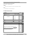
If X1 is selected in Table IV of the Model Selection Guide, then the 4908 Conductivity Cell has been pre-
mounted by Honeywell onto the support tube. Also cable wiring to the universal head terminal board has
been completed. The valve assembly can then be mounted to the process by following steps under
“Mounting into the Process” mentioned earlier.
3.4 Insertion
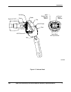
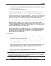
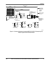
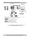
1. Make sure the bushing and washer (Fig. 1-5) are in place on the support tube. A thin film of silicone
grease is applied at the factory to the bushing and to the support tube area covered by the compression
handle. If this film has been wiped off or if dirt or grit is present, clean these areas and reapply a new
film of silicone grease (p/n 090011, 0.3 oz. tube).
2. Obtain the cell and support tube assembly prepared earlier. Separate the compression handle from the
support grip by turning the support grip counterclockwise approximately two turns. Slide the
compression handle along the support tube until the bushing and washer are sandwiched between the
handle and 4908 Cell Adapter.
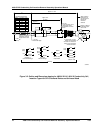
3. Slide the cell and tube assembly into the removal device housing and tighten the compression handle
clockwise until drag is felt on the tube. This can be determined by rotating the tube by hand.
4. REDUCE PROCESS PRESSURE TO 50 PSIG OR LESS. Open the ball valve; handle parallel to
valve.
5. Push the cell and support tube assembly all the way in using the support grip.
6. Tighten the support grip by turning clockwise two turns.
ATTENTION
This step is important to prevent blow-back of cell and support tube assembly. The bushing acts as a safety
stop against the cell adapter if the support tube does blow back.
7. Return the process to normal operating pressure.
8. Further tighten the compression handle if leakage occurs from the bushing seal area.


