


4909 CPVC Conductivity Cell Insertion/Removal Assembly Operations Manual
16 4909 CPVC Conductivity Cell Insertion/Removal Assembly– Operations Manual 7/99
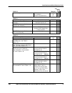
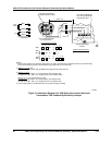
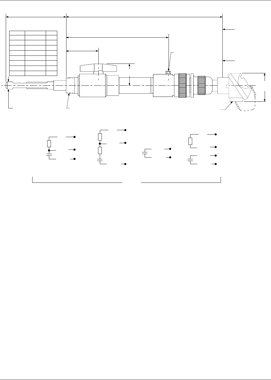
2.5"
(64mm)
Approx 4.1"
(105mm)
Approx 12.5"
(317mm)
X "
See Below
Approx 19.7" max.
(502mm)
Allow a minimum
clearance of 36"
(914 mm) beyond
this point for
removal of
electrode.
Allow 42" (1067mm)
if alternate support
tube is used.
1/4" NPT
Purge connection. Do not
exceed Temp./Press.
specifications of removal
device
1-1/2" NPT
Schedule 80 Nipple
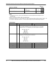
Suffix A
001
0 1
1
5
1 0
20
25
50
X" Approx.
5.5
5.5
5.5
4.5
5.7
6.0
6.8
6.8
mm
140
140
140
114
145
152
173
173
* Standard Insertion Depth
* Add 6" (152 mm) to
Dimensions if 074344
Support Tube is Used.
0.940"
(24mm)
Dia
3"
(76mm)
1/2" female NPT for user’s
flexible electrical conduit
connection. For insertion or
removal of cell, disconnect
conduit connections.
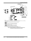
RED
WHITE
BLACK
Linear Micromho,
Resistivity, or
Concentration Ranges
Temp.
Comp.
Cell
RED
WHITE
BLACK
Shunt
Comp.
Series
Comp.
Cell
Non-Linear
Micromho Ranges
WHITE
BLACK
Without Temp.
Compensation
WHITE
BLACK
RED
GREEN
Cell
Cell
Temp.
Comp.
Linear Ranges
Cell Wiring
a/n 23346
(Table III = 333)
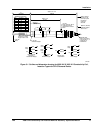
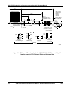
Figure 3-2 Outline and Dimension drawing for 4909-X-X-X-X1-03-X-X Conductivity Cell,
Insertion Type with CPVC Removal Device and Universal Head