


Platinization and Platinum Black
7/99 4909 CPVC Conductivity Cell Insertion/Removal Assembly– Operations Manual 21
A
A D
C
B
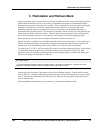
View of Junction Box Head
with Cap Removed
WHITE
BLACK
RED
GREEN
Cell
Temp.
Comp.
B
D
C
A
Internal Cell Assembly
Configuration
W
K
SH
G
R
Coax Cable
Shield
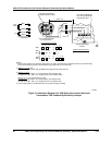
Conductivity/Resistivity
Analyzer
A
n a l y ze r I np u t C on n e c ti o n s
B
C
1000 ft. max.
Note 3
Note 2
Four Point Terminal Plate
with #6-32 Screw Terminals
Five Point Terminal Board.
Each Terminal Will Accept
#16 Gage Max. Wire
Note 1
GND
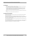
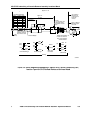
NOTES:
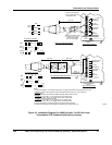
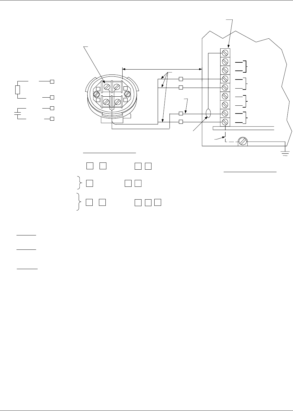
1. For pure water samples in non-conductive (plastic, glass, etc.) piping, ground the black cell electrode lead near the cell. Alternatively,
connect to the 9782 ground screw as shown dotted. Do not ground 10, 25, or 50 constant cells.
2. 9
7 8 2C - S 0 (only)
Use 22 gage minimum coaxial cable type RG59/U connecting shield to terminal "SH" only.
3. 9
7 8 2 C - S 0
For cable runs of up to 500 ft., use: 18 gage minimum, three conductor cable.
For cbale runs of 500 - 1000 ft., use: 16 gage minimum, three conductor cable.
9
78 2C - W0 [coax and shield (SH) not used]
For cable runs of up to 500 ft., use: 18 gage minimum, four conductor cable.
For cable runs of 500 - 1000 ft., use: 16 gage minimum, four conductor cable.
4. Cell to analyzer cables are considered low level. Run seperate from high level wiring.
5. If 2 Cells are to be appplied, the same wirin
g
g
uidelines are applied to Cell 2 as are followed for Cell 1.
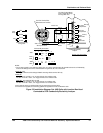
C
e l l A s s e mb l y Co n n e ct i o n s
4905
IIIIII IV
V
VI
- - 333 - X1
4973
4974
III III
IV
- 333 - X1 -
V
4908
I II III IV V VI
- - 333 - X1
4909
VII
K
W
G
R
#2 Temp
Compensator
#1 Temp
Compensator
Cell 2
Electrodes
Cell 1
Electrodes
D
(Note 5)
(Note 5)
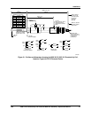
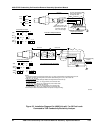
Figure 5-2 Installation Diagram-Cat. 4909 Cells with Junction Box Head
Connected to 9782 Conductivity/Resistivity Analyzer