


Installation Manual
SSB RADIOTELEPHONE
FS-5070
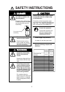
SAFETY INSTRUCTIONS ......................................................................................................................i
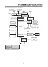
SYSTEM CONFIGURATION..................................................................................................................ii
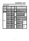
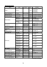
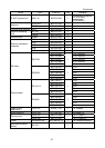
EQUIPMENT LIST................................................................................................................................. iii
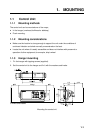
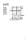
1. MOUNTING.................................................................................................................................... 1-1
1.1 Control Unit............................................................................................................................. 1-1
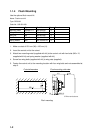
1.2 Antenna Coupler..................................................................................................................... 1-3
1.3 Transceiver Unit...................................................................................................................... 1-9
1.4 Handset Hanger ................................................................................................................... 1-10
1.5 Antenna................................................................................................................................. 1-10
1.6 Mounting of Optional Equipment...........................................................................................1-11
2. WIRING .......................................................................................................................................... 2-1
2.1 Wiring...................................................................................................................................... 2-1
2.2 External Equipment ................................................................................................................ 2-7
2.3 AC-DC Power Supply Unit PR-850A (Option).......................................................................2-11
2.4 Automatic Antenna Switch (Option)...................................................................................... 2-13
3. INITIAL SETTING........................................................................................................................... 3-1
3.1 Performance Check................................................................................................................ 3-1
3.2 Initializaing Control Unit and Transceiver Unit ....................................................................... 3-1
3.3 Manual 2182 kHz Tuning Preset............................................................................................ 3-3
3.4 System Setup ......................................................................................................................... 3-5
3.5 Setting DIP Switches............................................................................................................ 3-12
3.6 Preamp Setting (For FAX-5) Switches ............................................................................... 3-13
4. OPTION KIT ................................................................................................................................... 4-1
4.1 Antenna BK Relay .................................................................................................................. 4-1
4.2 DSC Routine Frequency Board.............................................................................................. 4-3
4.3 Signal Splitter Board............................................................................................................... 4-4
4.4 Connecting of NBDP Terminal Unit OP05-100 (IB-583) ........................................................ 4-5
4.5 Dummy Load .......................................................................................................................... 4-5
PACKING LISTS.................................................................................................................................A-1
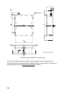
OUTLINE DRAWINGS .......................................................................................................................D-1
INTERCONNECTION DIAGRAM ......................................................................................................S-1
www.furuno.co.jp
All brand and
p
roduct names are trademarks
,
re
g
istered trademarks or service marks of their res
p
ective holders.