


2-7
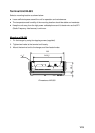
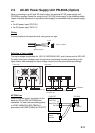
2.2 External Equipment
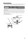
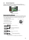
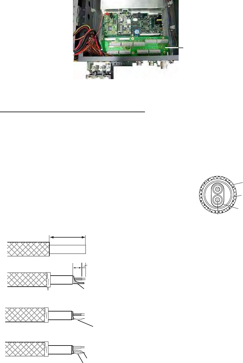
Cables for the external equipment are connected to the TB Board (05P0758) in the
transceiver unit and ports on the control unit Note that these cables should be fixed to the
cable board at the entrance of cables with cable ties.
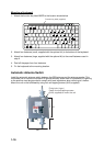
TB Board
(05P0758)
Transceiver unit, inside view
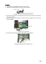
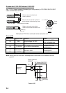
Equipment with IEC 61162-1 (NMEA) format
Connects a navigator to the terminal board in the transceiver unit. The FS-5070 can receive
the following sentences in IEC-61162-1 (ed.2nd) format. Use the interconnection cable type
TTYCS-1 (Japan Industrial Standard type, or equivalent) or CO-SPEVV-SB-C 0.2x2P.
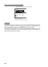
• GLL: Latitude and longitude
• RMC: GPS generic navigation information
• GGA: GPS position, UTC
• ZDA: UTC, day, month, and year
• RMA: Minimum Loran-C data
Priority: GGA>RMC>GLL>RMA
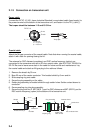
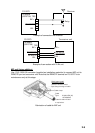
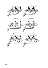
90
11
9
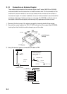
Twist and trim the shield.
Inner sheath
Remove the armor by 90 mm.
Remove the inner sheath by 20 mm,
and the sheath of the cores by 9 mm.
Solder a vinyl wire to the shield.
Vinyl wire
Wind vinyl tape.
Armor
Vinyl wire
Soldering
Solder a vinyl wire to the shield.
Solder the shield and unused cores.
(For CO-SPEVV-SB-C 0.2x2P)
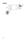
Fabrication of TTYCS-1 for connection to the transceiver unit
Conductor
S = 0.75 mm
φ = 1.11 mm
2
TTYCS-1 (Twisted pair cable)
Armor
Shield
Sheath
φ =
10.1 mm