


2-4
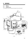
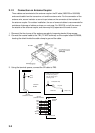
2.1.3 Connection on transceiver unit
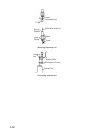
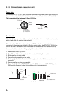
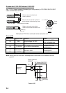
Power cable
Connect the DPYC-10 (JIS, Japan Industrial Standard) or equivalent cable (local supply) to
the power terminal at the bottom of the transceiver unit, and fasten it to the TB (+) and (-).
The torque should be between 11.5 and 15.5 N·m.
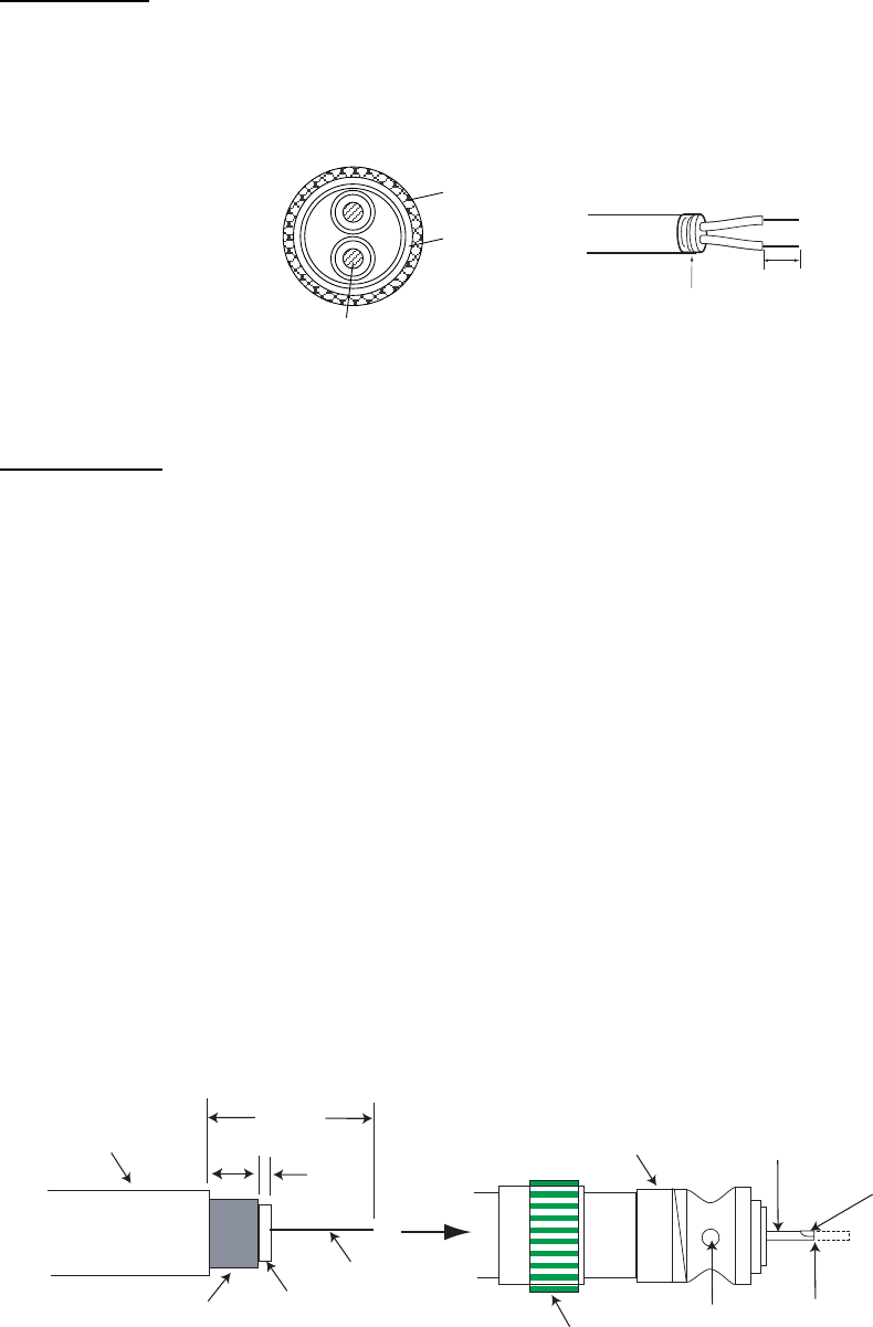
Conductor
S = 10 mm
φ = 4.05 mm
2
DPYC-10
Armor
Sheath
φ =
17.1 mm
22 mm
Vinyl tape
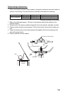
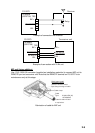
Coaxial cable
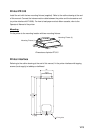
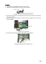
Attach the M-type connector of the coaxial cable. Note that when running the coaxial cable,
attach it with slack for opening/closing the lid.
The antenna for DSC distress (mandatory) and DSC routine frequency (option) are
connected to the transceiver unit with a 50 ohm coaxial cable, type RG-10/UY, RG-8A/U or
3D-2V. Be sure to leave some slack in the cable for future service and maintenance. Lay
the coaxial cable and attach an M-type plug to the cable as follows.
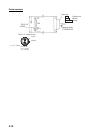
1. Remove the sheath by 30 mm.
2. Bare 23 mm of the center conductor. Trim braided shield by 5 mm and tin.
3. Slide coupling ring onto cable.
4. Screw the plug assembly on the cable.
5. Solder plug assembly to braided shield through solder holes. Solder contact sleeve to
conductor.
6. Screw coupling ring into plug assembly.
7. Screw the plug into the D. ANT (W/R 1) port for DSC distress and ANT (W/R 2) port for
DSC routine frequency (option) at the bottom of the transceiver unit.
Sheath
30 mm
5 mm
2 mm
Conductor
Insulator
Braided shield
Plug assembly
Contact sleeve
Cut conductor here.
Solder both
sides of hole.
Coupling ring
Solder here.