


- 24 -
LGE Internal Use Only Copyright © 2010 LG Electronics. Inc. All right reserved.
Only for training and service purposes
3. TECHNICAL BRIEF
ͽͶ͑ͺΟΥΖΣΟΒΝ͑ΆΤΖ͑ΟΝΪ
YZVXZZ
3. TECHNICAL BRIEF
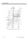
3.2.1 Power on and startup
̲ Analog startup Circuit
Because the POR circuit and the LPBG are directly connected to the battery, it is not possible to switch
them off. If the battery voltage exceed the power on reset threshold (2.5V), the power on reset is released,
the LPMU regulator and the LRTC voltage regulator are switched on. The LPMU regulator starts in its
ultra-low power mode.
The LPMU regulator generates a control signal (lpmu_OK) that enables the 50KHZ PMU oscillator. The
output clock of the oscillator is checked with a fully coded counter. A counter overflow releases the reset
(vpmu_rst_n) signal for the small PMU state-machine.
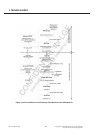
̲ Small first digital State-Machine
The small PMU state-machine is always connected to VPMU After starting from reset the small startup
state machine enters the SYSTEM OFF state and only continuous the startup procedure if a switch on
event like first connect, on-key, wake up or charge detect occurs.
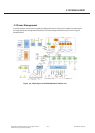
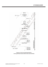
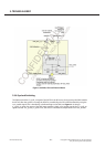
̲ PMU-main State-Machine
The main PMU state-machine is always connected to VPMU also. The power up sequence driven by the
PMU state-machine can be seen in Figure18. After enabling the reference (HPGB) and waiting for the
settling time, the battery voltage is measured and compared with the power on threshold. If the battery
voltage is high enough, the SD1 DC/DC converter and the LCORE LDO are started. A timer ensures that
the supply voltage will be stable before the DCXO is enabled. The DCXO settling time is ensured using a
fixed timer. After an overflow of this timer, the reset is released for the rest of the system. The PMU state
machine remains in this System-ON state until the system is switched into the OFF state. For example the
system sleep mode is completely configured by software( for example switching off the LDO’s, switching
of the DCXO etc.) and controlled by the VCXO_enable signal. The reason for the startup is stored in the
ResetSourceRead register.
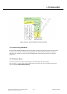
̲ Battery Measurement
The ADC and the oscillator for the ADC needs the VDD_ADC supply voltage from the LADC LDO. LADC
uses either the charger voltage VDD_CHARGE or VDDRTC as input voltage. The input voltage is selected
automatically by a bulk switch circuit. LADC, the ADC and the oscillator are enabled on request for every
battery measurement if the charger unit is not running. This is handled by an ADC control block in one of
the state-machines. If the charger unit is running the ADC is controlled by the charger state-machine