


- 27 -
Copyright © 2010 LG Electronics. Inc. All right reserved.
Only for training and service purposes
LGE Internal Use Only
3. TECHNICAL BRIEF
ͽͶ͑ͺΟΥΖΣΟΒΝ͑ΆΤΖ͑ΟΝΪ
26/133
3. TECHNICAL BRIEF
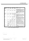
3.2.2 Switching on due to first connect
If the battery voltage is connected the first time, that means the system enters the first time the SYSOFF
state, this is stored in a first connect flag. If the first connect flag is set, the system will start immediately
and not wait for any other system on event in the SYSOFF state.
3.2.3 Switching on due to on-Key event
The on key is connected to the ONKEY pad. The ESD protection and the input structure of this pad are
connected to VRTC. If the ONKEY pad is forced to VRTC by an external key or similar circuit, the system
starts. The ONKEY is sampled with the PMU clock. It has to be sampled four times high before a valid on
event is generated. The status of the ON key can be read in the PMU registers, so it can be used as a
functional key during phone operation also.
3.2.4 Switching on due to RTC alarm
The real time clock can generate a wakeup signal called RTC alarm. This signal is sampled from the state-
machine and after successfully detecting a high, the system is switched on.
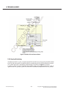
3.2.5 Switching on due to charging
When a battery with a voltage below the SSONLEV level is inserted, the state machine will not start the
system. As long as the battery voltage stays lover than SYSONLEV the system will stay off. The only
possibility to start up the system is due to an external charger.
If an external charger is connected and detected and the battery is charged above the SYSONPRE voltage
level the system will start up.
The PMU main state machine waits in the Check battery state until the battery voltage condition is
fulfilled. The charger state machine provides the necessary pre-charge indication signal. This pre-charge
signal is denounced in a small counter to have a stable signal. This is important, especially in half/full-
wave charging where the charger detection is switching between charger detected/not detected
according the AC supply frequency. Reasons for details on pre-charging see the charger chapter. The
charger is controlled by an independent state machine. The pre-charge signal is used to trigger the pre-
charge signal is used to trigger the pre-charge functionality. The charger state machine fully control the
pre-charge, the PMU-state machine now changes to state HPBG on state and the system starts. This state
change is indicated to the charger state-machine to enable the charger watchdog for safety
ͽͶ͑ͺΟΥΖΣΟΒΝ͑ΆΤΖ͑ΟΝΪ
Y^VXZZ
3. TECHNICAL BRIEF
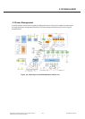
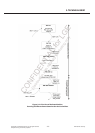
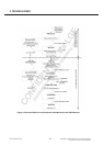
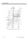
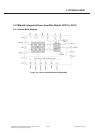
3.2.6 Power Supply Start-up sequence
In order to avoid an excessive drop on the battery voltage caused by in-rush current during system
power-on, possibly leading to system instability and “hick-ups” a staggered turn-on approach for the
regulators is implemented. The regulators are turned on in a well defined sequence, thus spreading the
in-rush current transients over time.
The IO’s of X-GOLD TM 213 are isolated in OFF mode (core supply is off). The isolation signal is
controlled by the PMU state machine. This ensures that the PADs are in a well defined state during core
supply settling. This allows to power up the LCORE core regulator and wait for the core to reach reset
state before powering up the I/O supply regulators.