38 Rockwell Automation Publication 1412-UM001D-EN-P - September 2012
Chapter 3 Display Modes
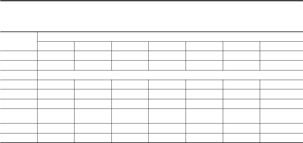
This table lists the capture threshold levels, based on the probe in use (for the
current channels) and voltage at the different percent selections.
Transients are detected by comparing all 256 samples on the current cycle with
their counterparts from the previous cycle for each active input channel. Should
any one sample deviate from its counterpart by the selected percentage value in
the set up, this will be considered a transient and the data will be captured.
When capture occurs, four cycles are recorded for each input. These include the
trigger cycle, the previous cycle to the trigger and the two cycles that follow the
triggered cycle. All active inputs will be captured.
Thresholds
100% 50% 20% 10% 5% 2% 1%
MN93 200 A 100 A 40 A 20 A 10 A 4 A 2 A
MN193 (100A) 100 A 50 A 20 A 10 A 5 A 2 A 1 A
MN193 (5A) [(primary x 5) ÷ (secondary)] x (percent x 100)
SR193 1000 A 500 A 200 A 100 A 50 A 20 A 10 A
AMPFLEX 193 2900 A 1400 A 580 A 290 A 140 A 58 A 29 A
MR193 1000 A 500 A 200 A 100 A 50 A 20 A 10 A
2999A Ratio
Adapter
3000 A 1500 A 600 A 300 A 150 A 60 A 30 A
1A Ratio Adapter 1 A 0.5 A 0.2 A 0.1 A 0.05 A 0.02 A 0.01 A
Voltage 480V 240V 96V 48V 24V 9.6V 4.8V


