ES-2048 User’s Guide
156 Chapter 19 Multicast
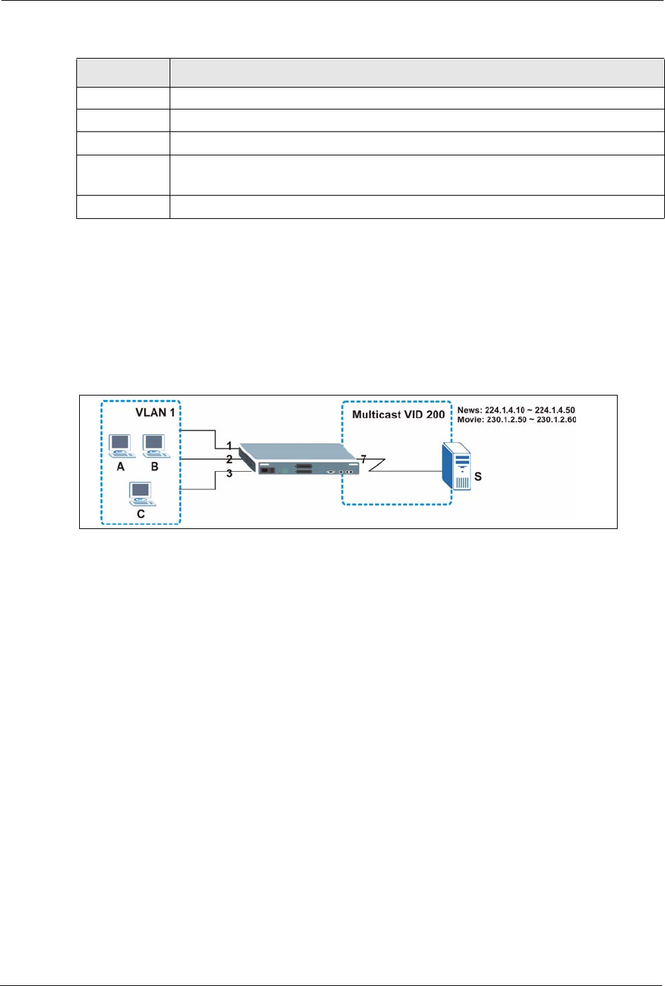
19.7.1 MVR Configuration Example
The following figure shows a network example where ports 1, 2 and 3 on the switch belong to
VLAN 1. In addition, port 7 belongs to the multicast group with VID 200 to receive multicast
traffic (the News and Movie channels) from the remote streaming media server, S. Computers
A, B and C in VLAN 1 are able to receive the traffic.
Figure 65 MVR Configuration Example
To configure the MVR settings on the switch, create a multicast group in the MVR screen and
set the receiver and source ports.
Name This field displays the descriptive name for this setting.
Start Address This field displays the starting IP address of the multicast group.
End Address This field displays the ending IP address of the multicast group.
Delete Select Delete All and click Delete to remove all entries from the table.
Select Delete Group and click Delete to remove the selected entry(ies) from the table.
Cancel Select Cancel to clear the checkbox(es) in the table.
Table 43 MVR: Group Configuration
LABEL DESCRIPTION


