Dolphin® 9500 Series User’s Guide Rev A
5/15/07
12 - 7
The HomeBase can now transfer data between the terminal and the host device. If communication does not occur, check the
port connections to ensure that the cradle is correctly configured.
Verifying Communication
You can verify that the USB driver is functioning by watching the COMM LED on the USB HomeBase. When the COMM LED
illuminates solid green, the HomeBase is communicating with the host device.
Verifying Data Transfer
The COMM LED flashes when data is being transferred via the HomeBase. For an RS-232 connection, the COMM LED flashes
red and green. For a USB connection, the COMM LED flashes green.
RS-232 Communications Cables
Connecting the Cables
Connect the HomeBase to the host computer or other device by plugging an RS-232 serial cable into the RS-232
Communications Port on the rear of the HomeBase. The wiring of your cable depends on whether the other device is set up as
a Data Communications Equipment (DCE) or Data Terminal Equipment (DTE) device.
The HomeBase Communication Port is configured as a DCE device. To communicate with a DCE device, use either a null
modem adapter in line with a standard RS-232 cable, or a null-modem serial cable. To communicate with a DTE device such as
a computer, use a standard (or straight-through) RS-232 cable.
You can make your own cables by following the pin configuration in the chart below. To do so, you must determine if your host
RS-232 device is 9-pin or 25-pin, and whether it is configured as a DCE or DTE device.
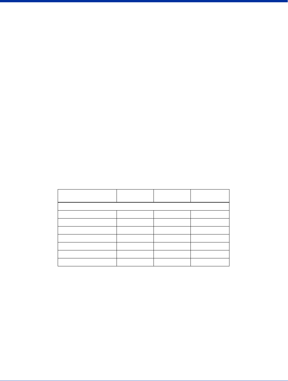
RS-232 Pin Configuration
Note: The Dolphin 9500 Series HomeBase cannot be daisy-chained.
HomeBase /Host Port
(DCE)
IBM AT DB9
(DTE)
IBM XT
DB25 (DTE)
Modem DB25
(DCE)
Pin / Input Signal
2 / (RD) 2 3 2
3 / (TD) 3 2 3
5 / (SG) 5 7 7
4 / (DTR) 4 20 6
6 / (DSR) 6 6 20
7 / (RTS) 7 4 5
8 / (CTS) 8 5 4


