ES-4024A User’s Guide
Chapter 23 VRRP 147
CHAPTER 23
VRRP
This chapter shows you how to configure and monitor the Virtual Routing Redundancy
Protocol (VRRP) on the ES-4024A.
23.1 Overview
Each host on a network is configured to send packets to a statically configured default gateway
(the ES-4024A). The default gateway can become a single point of failure. Virtual Routing
Redundancy Protocol (VRRP), defined in RFC 2338, allows you to create redundant backup
gateways to ensure that the default gateway of a host is always available.
In VRRP, a virtual router (VR) represents a number of physical layer-3 devices. An IP address
is associated with the virtual router. A layer-3 device having the same IP address is the
preferred master router while the other Layer-3 devices are the backup routers. The master
router forwards traffic for the virtual router. When the master router becomes unavailable, a
backup router assumes the role of the master router until the master router comes back up and
takes over.
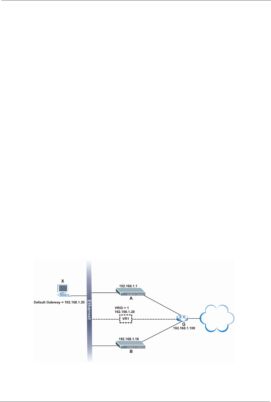
The following figure shows a VRRP network example with the switches (A and B)
implementing one virtual router VR1 to ensure the link between the host X and the uplink
gateway G. Host X is configured to use VR1 (192.168.1.20) as the default gateway. If switch
A has a higher priority, it is the master router. Switch B, having a lower priority, is the backup
router.
Figure 76 VRRP: Example 1
If switch A (the master router) is unavailable, switch B takes over. Traffic is then processed by
switch B.


