4-102
Screens
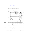
Pwr Ramp: Summary
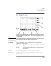
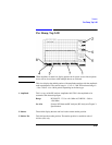
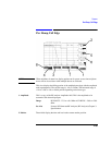
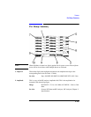
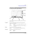
3. Flatness This field displays the positive and negative amplitude peaks relative to the average
power over the useful bits in the measured burst.
• Pk+ peak, relative to the average power.
• Pk− is the negative amplitude peak, relative to the average power.
See Also Keys: ON/OFF, HI LIMIT, LO LIMIT, REF SET, AVG, Units
4. Measurement
Summary
This field displays whether HI/LO limits set for the measurement display fields,
(Ampl1-12 and flatness) were exceeded in the last measurement.
See Also Making Measurements: Solving Problems, Messages
5. Pk TX Pwr This field displays the average transmitted power over the useful bits in the
measured burst. It is measured from the center of the first useful bit to the center of
the last useful bit. This measurement is only available when using the RF IN/OUT
port.
See Also Keys: ON/OFF, HI LIMIT, LO LIMIT, REF SET, AVG, Units
6. SyncStatus This field displays any errors that occurred while trying to synchronize to the
demodulated data. During multi-burst measurement, this field indicates the
measurement progress. When the measurement is complete, the SyncStatus is
displayed.
See Also Making Measurements: Solving Problems Messages
7. Time1-12 These fields select the time (relative to the center of bit zero) the amplitude will be
measured on the amplitude envelope. Bit zero is the first useful bit in the measured
burst.
Range −50.0 to +593.0 µs.
8. Trig Delay This field sets the time delay between a valid trigger event and the beginning of a
measurement.
Range 0 to 5000.00 µs.


