


Chapter 5 Serial Functions
101
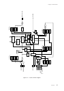
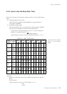
5-3 Half-duplex UART Serial Interface
5-3-1 Overview
Setup and operation of UART transmission and reception are described
below.
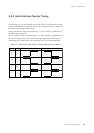
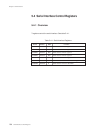
5-3-2 Setup and Operation
■ Transmission
(1) Select UART by setting the SC0CMD flag of the serial interface 0 control
register (SC0CTR) to "1."
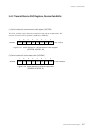
(2) Specify the first bit to be transferred (MSB first or LSB first) with the
SC0DIR flag of the serial interface 0 mode register 0 (SC0MD0).
(3) Select the valid edge of the clock signal with the SC0CE1 to 0 flags of the
SC0MD0 register.
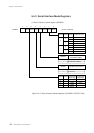
(4) Select the clock source with the SC0CK1 to 0 flags of serial interface 0
mode register 1 (SC0MD1).
(5) Set the SC0CKM flags of the SC0MD1 register to "1" to divide the clock
source frequency by 8.
(6) Set the SC0NPE flag of the serial interface 0 mode register 2 (SC0MD2) to
enable or disable parity.
Half-duplex UART Serial Interface
When the serial port is enabled
and the SC0CE1 to 0 flags of
the SC0MD0 register are
toggled, the transfer bit count
may change.
The TXD pin goes to a high
level after transmission is
complete.
Setting the SC0FM flag of the SC0MD2 register to frame
mode automatically sets the SC0LNG2 to 0 flags of the
SC0MD0 register.
After the transfer is complete, the SC0LNG2 to 0 flags of the
SC0MD0 register are automatically set with the transfer bit
count.
Set the SC0CKM flag of the SC0MD1 register to "1" to divide
the clock source frequency by 8.