


Chapter 7 AC Zero-Cross Circuit/Noise Filter
123
AC Zero-Cross Circuit Operation
7-2 AC Zero-Cross Circuit Operation
7-2-1 Setup and Operation
Settings for zero-cross circuit operation are listed below.
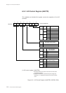
(1) Set the REDG1 flag of the IRQ1ICR register to select the valid edge for IRQ1.
(2) Set the NF1EN and NF1CK1 to 0 flags of the NFCTR register to set the noise filter
and its sampling clock.
(3) With the P21IM flag of the FLOAT1 register, set the P21 pin to zero-cross
detection.
(4) An IRQ1 interrupt is generated by the falling edge or the rising edge of AC
zero-cross detection output.
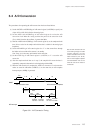
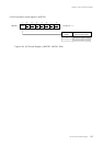
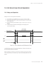
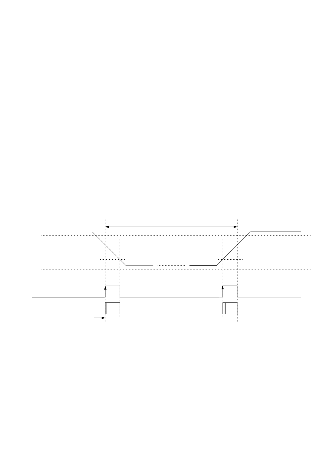
Actual IRQ interrupt requests will be generated multiple times. Therefore, the software must
filter this signal before making any evaluations.
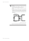
When noise filtering is selected for use, the amount of evaluation processing by the software
will be reduced. However, if the OSC stops, a return from the backup mode will not be
possible.
VDD
VSS
AC line waveform
Point A
Ideal
IRQ1
Actual
IRQ1
10 ms at 50Hz
8.3 ms at 60Hz
Figure 7-2-1 AC Line Waveform and IRQ Generation Timing