


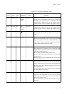
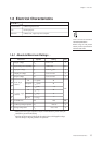
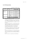
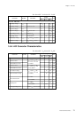
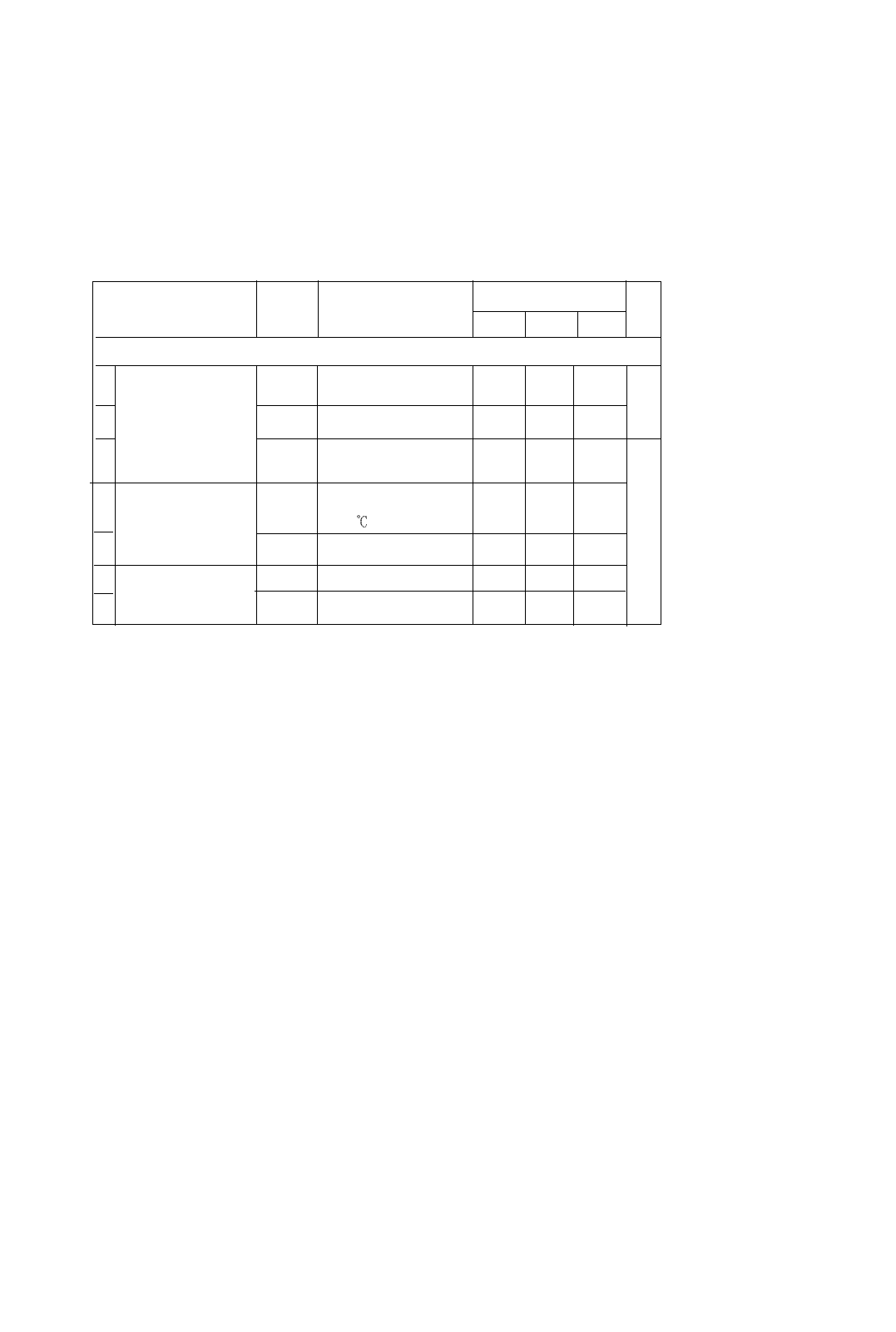
1-5-3 DC Characteristics
Ta=–40 to +85°C V
DD
=2.0 to 5.5V V
SS
=0V
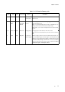
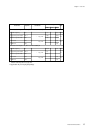
Notes:
∗
1
Measured under conditions of Ta=25°C and no load.
The supply current during operation, I
DD1
(I
DD2
), is measured under the
following conditions: After all I/O pins are set to input mode and the oscillation
is set to <NORMAL mode>, the MMOD pin is fixed at V
SS
, the input pins are
fixed at V
DD
, and a 20MHz (8.39MHz) square wave of amplitude V
DD
,V
SS
is input
to the OSC1 pin.
The supply current during operation, I
DD3
, is measured under the following
conditions: After all I/O pins are set to input mode and the oscillation is set to
<SLOW mode>, the MMOD pin is fixed at V
SS
, the input pins are fixed at V
DD
,
and a 32.768kHz square wave of amplitude V
DD
,V
SS
is input to the XI pin.
The supply current during HALT mode, I
DD5
(I
DD6
), is measured under the
following conditions: After all I/O pins are set to input mode and the oscillation
is set to <HALT mode>, the MMOD pin is fixed at V
SS
, the input pins are fixed
at V
DD
, and an 32.768kHz square wave of amplitude V
DD
,V
SS
is input to the XI
pin.
The supply current during STOP mode I
DD7
(I
DD8
) is measured under the following
conditions: After the oscillation mode is set to <STOP mode>, the MMOD pin is
fixed at V
SS
, the input pins are fixed at V
DD
, and the OSC1 and XI pins are
unconnected.
*2
The items I
DD5
(I
DD6
) and I
DD7
(I
DD8
) are applicable only for 48-pin QFH package.
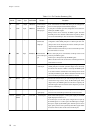
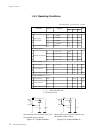
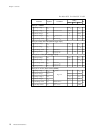
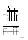
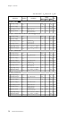
Parameter Symbol Conditions
Rating Unit
MIN TYP MAX
Supply current (no load at output)
∗
1
1 Supply current I
DD1
fosc=20.0MHz,V
DD
=5V
25 60
mA
2 during operation I
DD2
fosc=8.39MHz,V
DD
=5V 10 25
3I
DD3
*2
fx =32.768kHz,V
DD
=3V
100
4
Supply current during HALT mode
I
DD5
*2
fx =32.768kHz,V
DD
=3V 8
Ta=25
5I
DD6
*2
Ta=-40
to
85˚C µA
6
Supply current during STOP mode
I
DD7
V
DD
=5V, Ta=25˚C 0 2
7I
DD8
V
DD
=5V, Ta=-40
to
85˚C 0 20
Chapter 1 Overview
17
Electrical Characteristics
18