Chapter 2 Basic CPU Functions
31
Interrupts
PSW
New SP
(after interrupt is accepted)
7
0
PC8 to 1
PC16 to 9
PC18,17
HA7 to 0
HA15 to 8
PC0
Old SP
(before interrupt is accepted)
Low
Address
High
2-4 Interrupts
2-4-1 Accepting and Returning from Interrupts
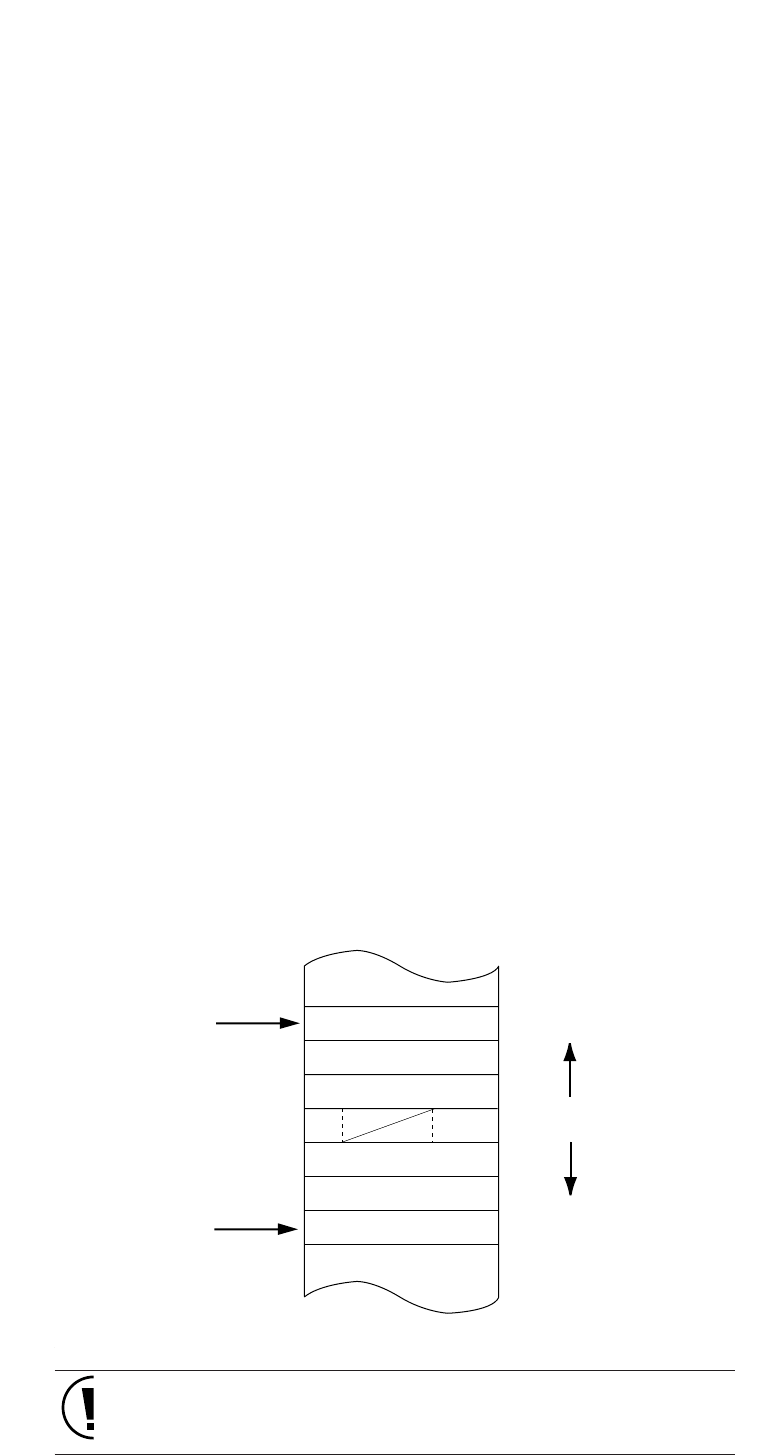
In the MN101C00 series, when an interrupt is accepted, the hardware
pushes the program's return address and the PSW, on to the stack, and
branches to the beginning address of the interrupt program specified by the
interrupt vector table.
■ Operation when Interrupt is Accepted
1. The stack pointer (SP) contents are update. (SP–6 → SP)
2. The handy address register (HA) is pushed on to the stack.
HA upper byte → (SP+5)
HA lower byte → (SP+4)
3. The program counter (PC = return address) contents are pushed on to the stack.
PC (bit 18
to
bit 17, bit 0) → (SP+3)
PC (bit 16
to
bit 9) → (SP+2)
PC (bit 8
to
bit 1) → (SP+1)
4. The PSW is pushed on to the stack.
PSW → (SP)
5. xxxLVn of the accepted interrupt is copied to IM of the PSW.
Interrupt level → IM
6. Execution branches to vector table.
Figure 2-4-1 Stack Status during an Interrupt
PSW
New SP
(after interrupt is accepted)
7
0
PC8 to 1
PC16 to 9
PC18,17
HA7 to 0
HA15 to 8
PC0
Old SP
(before interrupt is accepted)
Low
Address
High
Since the contents of data and address registers are not saved, use PUSH
instructions in the program to save these values as necessary on the
stack.


