


Chapter 1 23
Getting Started with AMPS Test
Display an FM Carrier Signal (Loopback Test)
Chapter 1
Getting Started with AMPS
Test
Display an FM Carrier Signal (Loopback Test)
Since an AMPS base station is basically a continuous wave (CW) FM
signal, this section will guide you through the process of generating and
displaying an FM signal at a cellular band frequency. It is intended to
make you feel more comfortable with using the Test Set. If you are
ready to begin testing, proceed to Chapter 2.
NOTE In the following operating example, you enter a common frequency for
the RF generator and RF analyzer to create and view the Test Set’s own
signal. However, typical AMPS base station testing uses channel
assignments with different transmit and receive frequencies. This is
explained further in "Using Channel Numbers to Set Analyzer and
Generator Frequencies" on page 68.
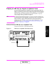
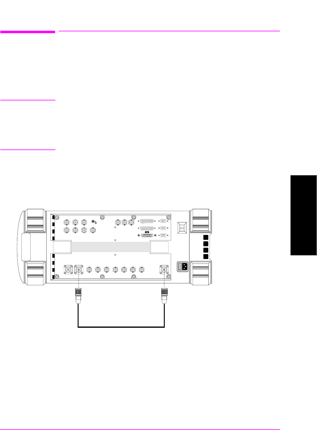
Connections for FM Carrier Loopback Test
Connect the Test Set in the following manner.
Figure 1-1 FM Carrier Loopback Test Connections
PARALLEL PORT
AUDIO OUT
MODULATION
INPUT
AUDIO IN
AUDIO
MONITOR
OUTPUT
EXT SCOPE
TRIG IN
VIDEO
OUT
ANT IN DUPLEX
CHIP CLOCK
1.2288
MHz OUT
FRAME
CLOCK
SYNC IN
EVEN
SECOND
TRIG/QUAL
IN
10 MHz
REF OUT
REF IN
RF IN/OUT
IN
BASEBAND OUT
HI LO
QI
PARALLEL PORT
SERIA PORT
SERIA PORT
SERIA PORT
16X
CHIP CLOCK
19.6608
MHz OUT
DUPLEX OUT
RF IN/OUT
Main Menu