


Chapter 3 65
Utility Procedures
Tracking Generator
Chapter 3
Utility Procedures
Tracking Generator
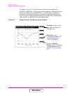
The tracking generator is typically used for measuring return loss and
insertion loss. It also allows for quick and accurate characterization of
filters, duplexers, combiners, and RF to IF conversions. Broadband RF
devices can be characterized with single sweeps due to the full-span
sweep capability to 1 GHz. The tracking generator also includes
amplitude and frequency offset. Output from the tracking generator are
provided at either the RF IN/OUT or DUPLEX OUT connector.
Using the Tracking Generator
To measure return loss, see "Measuring Swept Return Loss" on page 62.
To measure insertion loss, see "Measuring Insertion Losses" on page 51.
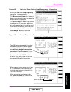
Features of the tracking generator are listed below.
• Sweep: the start and stop frequencies of the sweep are determined
by the spectrum analyzer’s Main menu. The Span determines the
band, and Center Freq defines the midpoint of the sweep.
• Offset Freq: sets the difference between the instantaneous
frequency of the tracking generator and the center frequency of the
spectrum analyzer. This value can be positive or negative.
• Amplitude: sets the amplitude of the signal.
• Norm/Invert: With Norm
, the tracking generator sweeps from low
to high frequencies. With Invert, it sweeps from high to low
frequencies.
NOTE The offset function is useful when looking at frequency translating
devices, or anytime you need to sweep around a frequency while
analyzing another. During normal operation, offset is set to 0.00.
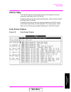
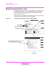
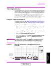
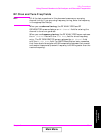
Figure 3-8 Spectrum Analyzer with Tracking Generator Controls
Displayed
Tracking
Generator
Controls
Main Menu