


Chapter 3 51
Utility Procedures
Measuring Insertion Losses
Chapter 3
Utility Procedures
Measuring Insertion Losses
To make accurate power and receiver measurements, the signal loss
through the cables or other devices used in your test setup must be
known and entered into the Test Set’s INSTRUMENT CONFIGURE
screen to compensate for these losses.
Signal losses are measured using a built-in automated routine that
runs on the Test Set’s IBASIC controller. Losses can be calibrated at a
discrete (single) frequency or over a frequency range. This is one
routine included in a set of utility procedures called the RF TOOLS.
During the test, a calibrated signal goes through two 6-dB
attentuators/pads (such as Mini-Circuits model NAT-6-60) and a short
type-N male-to-male cable to establish a known reference point. The
Test Set then prompts you to connect the device under test to measure
the additional loss through that device. (The pads and cable are not
part of the standard equipment shipped with the Test Set.)
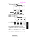
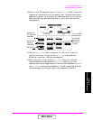
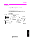
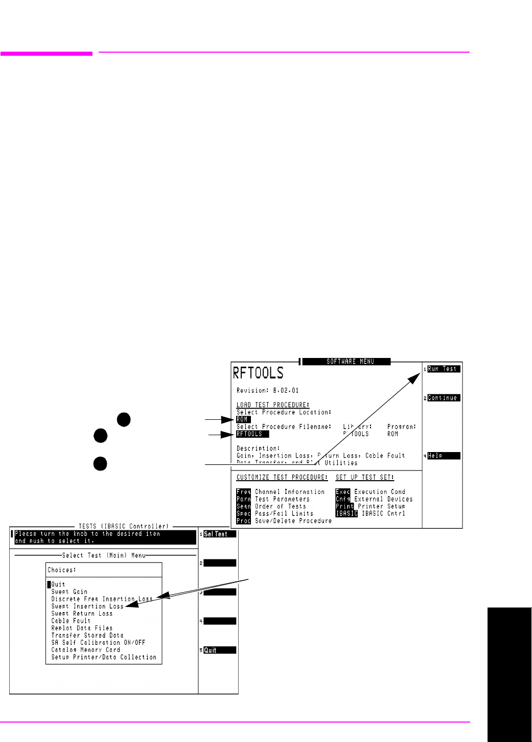
Figure 3-1 shows how to load and run the RFTOOLS routines and
select the desired insertion loss test.
Figure 3-1 Loading and Running the Insertion Loss Test
1 Select ROM.
2
Select RFTOOLS.
3
Select Run Test.
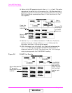
When the screen below appears.......
...use the knob to move the cursor and
select either Discrete Freq Insertion
Loss or Swept Insertion Loss. When
run, the test prompts you to enter the
necessary test frequency information
and displays setup diagrams. Make the
indicated connections and follow
instructions as you are prompted by the
program.
Main Menu