


34 Chapter 2
Testing AMPS Base Stations
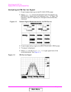
Transmitter Frequency Error/Offset and Power Test
Transmitter Frequency Error/Offset and Power Test
This test compares the measured center frequency of the base station to
the AMPS channel standard. The resulting difference is the frequency
error (also called the frequency offset). The measurement can be
displayed in frequency units (Hz, kHz, MHz) or in parts per million
(ppm). Measurements are made with all modulation turned off.
The transmitter’s power can be measured any time the transmitter is
keyed, but may not be accurate unless all modulation is turned off.
Transmitter power may be specified by the manufacturer in units of
watts (W), milliwatts (mW), dBm, Volts (V), or millivolts (mV).
Prerequisites
The following conditions must be met before testing:
❒ The Test Set is turned on and Preset was pressed to establish a
known instrument state.
❒ You have configured the Test Set for channel or frequency tuning as
necessary (see “Using Channel Numbers to Set Analyzer and
Generator Frequencies” on page 68).
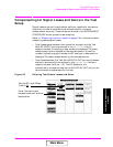
❒ You have specified any gains or losses in your test system (see
“Compensating for Signal Losses and Gains in the Test
Setup” on page 33).
Begin Testing
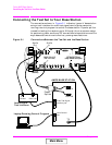
1. Turn off the base station’s RF transmitter. A transmitter can be
damaged if it is not transmitting into a specified load, such as an
antenna, power amplifier, duplexer, or power meter with a 50Ω
input impedance.
2. Verify that the transmitter’s rated RF power (or the level out of the
power amplifier if applicable) does not exceed the level printed next
to the Test Set’s RF IN/OUT connector.
3. Connect the transmitter’s RF output to the Test Set’s RF IN/OUT
port.
4. Turn off any modulation signals to the base station.
• Turn off the SAT tone.
• Turn off any data (digital) modulation signals.
• Turn off any audio (voice) modulation signals.
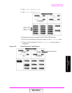
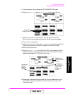
5. Press the
RF Anl key to access the RF ANALYZER screen.
6. Enter the transmitter’s RF Channel number.
Main Menu